


4-175
January 24, 2017
Removal and Installation
CLG835H
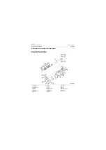
Steering hydraulic system
Removal steps
Figures
Operation instruction
Tools
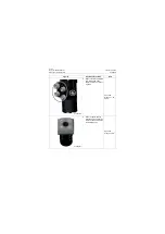
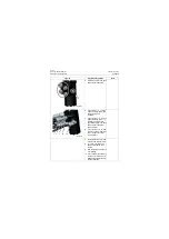
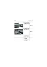
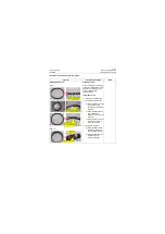
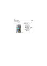
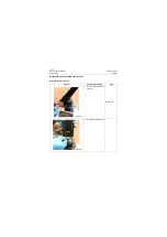
1. Fix the cylinder on assembly
stand using pin shaft hole of
cylinder head so that it can
not turn.
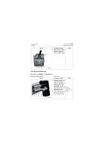
2. Install boosting rod on hook
spanner and unscrew cylin-
der head anticlockwise as
shown in the figure.
Hook spanner
Copper bar
Boosting rod
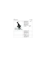
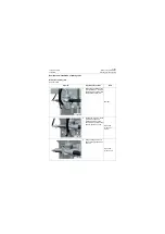
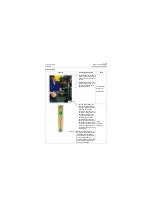
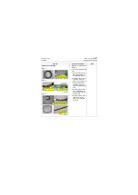
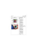
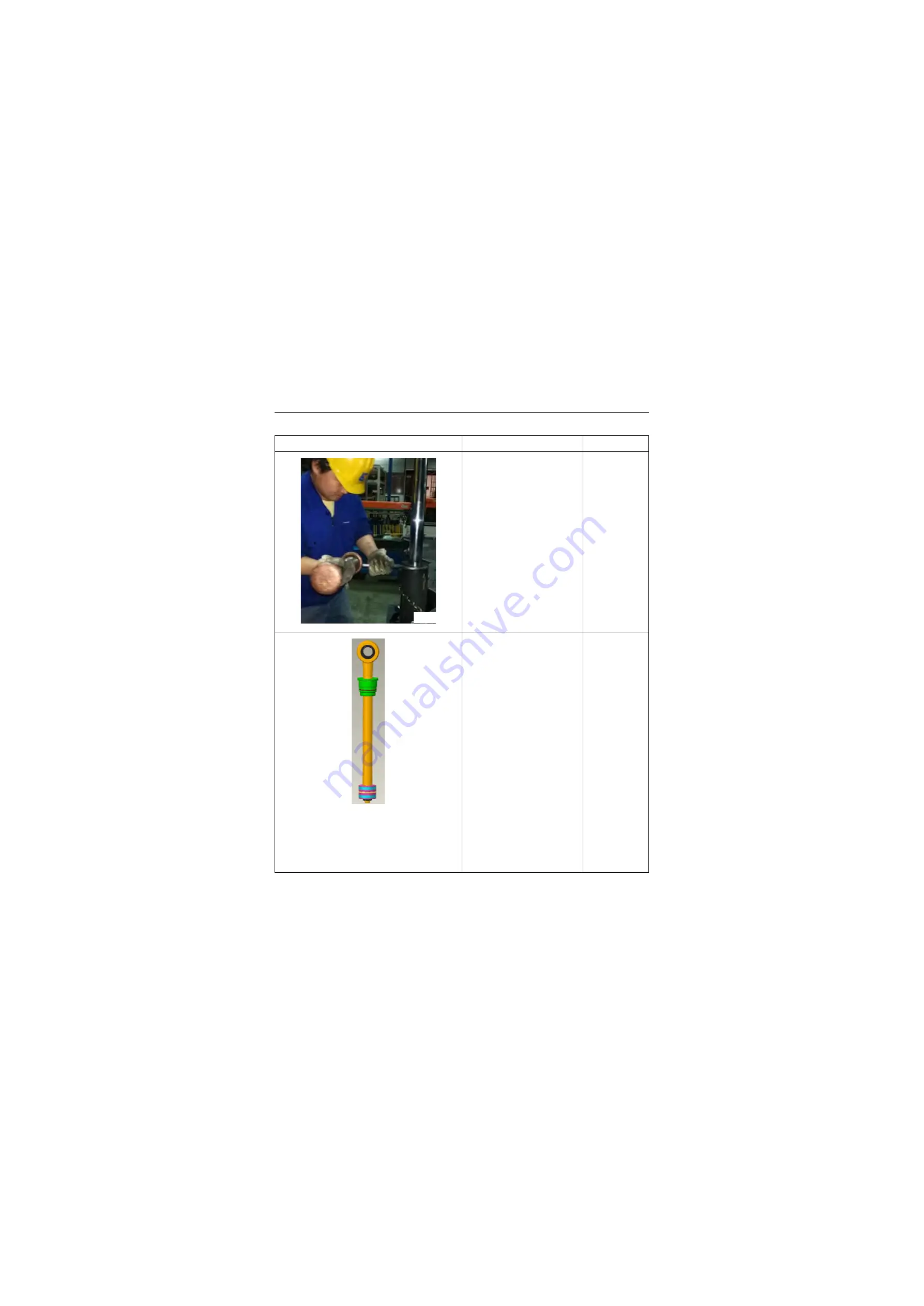
3. Put one end of lifting rope
through the piston rod lug
and fix it crosswise with the
other end on the lifting
equipment, and then con-
duct slow, uniform and verti-
cal lifting, place the piston
rod group horizontally on
special working position
apparatus after it (see left
figure) separates from cylin-
der block completely (Note:
the contact surface of work-
ing position apparatus and
the cylinder shall be made of
soft material.
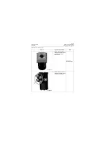
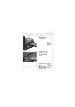
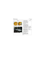
Note:
the contact surface of
working position apparatus and
the cylinder shall be made of
soft material. Put clean cotton
on the contact surface of
working position apparatus and
piston rod to prevent the rod
from being scratched.
Lifting
equipment
Lifting rope
P18H00262
P18H00263
Summary of Contents for CLG835H
Page 2: ......
Page 4: ...Contents January 24 2017 CLG835H...
Page 6: ...1 2 General Information January 24 2017 CLG835H...
Page 38: ...1 34 Machine Inspection Table January 24 2017 CLG835H...
Page 156: ...3 2 Power Train System January 24 2017 CLG835H...
Page 214: ...3 2 Power Train System January 24 2017 CLG835H...
Page 272: ...3 60 Testing and adjustment January 24 2017 Power Train Test CLG835H...
Page 276: ...4 4 Hydraulic System January 24 2017 CLG835H...
Page 552: ...6 2 Driver s Cab System January 24 2017 CLG835H...
Page 608: ...7 2 Structure January 24 2017 CLG835H...
Page 662: ...8 4 Electrical System January 24 2017 CLG835H...
Page 677: ...8 19 January 24 2017 Structure Function Principle CLG835H Power System P18E00014...


