4-186
Removal and Installation
January 24, 2017
Steering hydraulic system
CLG835H
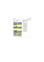
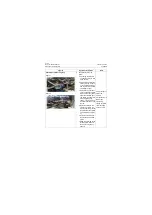
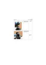
Figure 2
Figure 3
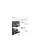
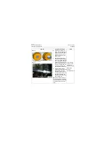
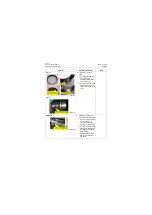
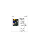
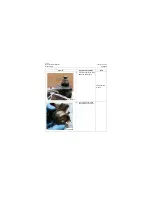
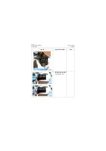
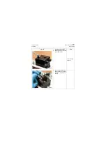
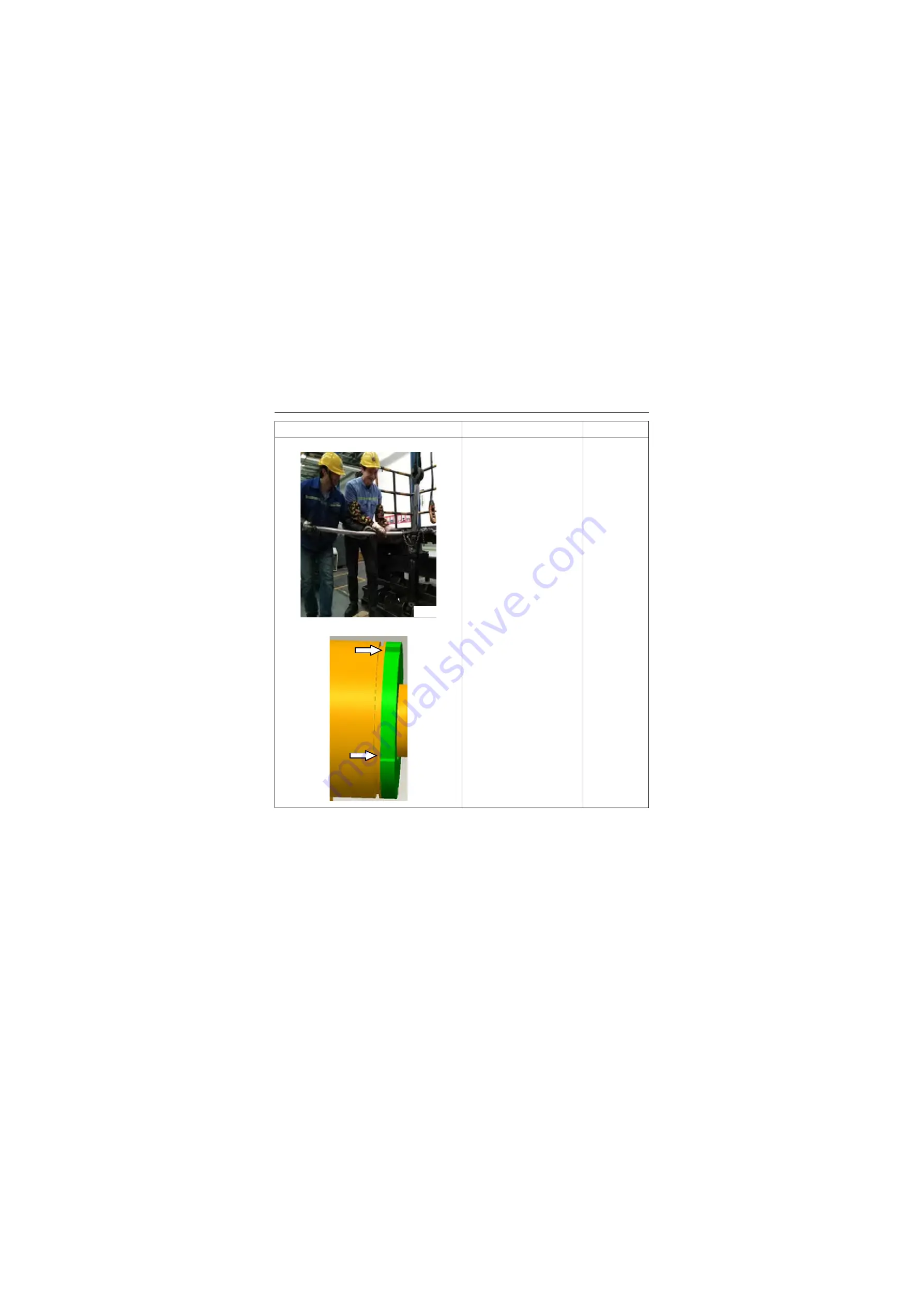
d. Knock the locking edge of
cylinder block into 4
square grooves of cylin-
der head using a punch
(with one sharp end and
one blunt end) in the
arrow direction shown in
Figure III (effect: locking).
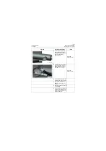
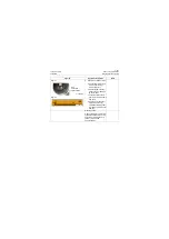
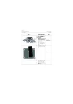
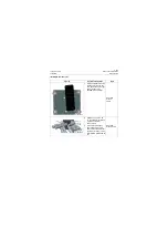
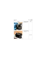
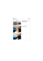
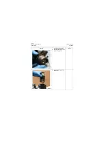
e. Seal the big and small
cavity of oil port with spe-
cial cap.
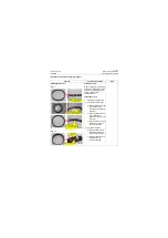
Figures
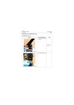
Operation instruction
Tools
P18H00283
P18H00284
Summary of Contents for CLG835H
Page 2: ......
Page 4: ...Contents January 24 2017 CLG835H...
Page 6: ...1 2 General Information January 24 2017 CLG835H...
Page 38: ...1 34 Machine Inspection Table January 24 2017 CLG835H...
Page 156: ...3 2 Power Train System January 24 2017 CLG835H...
Page 214: ...3 2 Power Train System January 24 2017 CLG835H...
Page 272: ...3 60 Testing and adjustment January 24 2017 Power Train Test CLG835H...
Page 276: ...4 4 Hydraulic System January 24 2017 CLG835H...
Page 552: ...6 2 Driver s Cab System January 24 2017 CLG835H...
Page 608: ...7 2 Structure January 24 2017 CLG835H...
Page 662: ...8 4 Electrical System January 24 2017 CLG835H...
Page 677: ...8 19 January 24 2017 Structure Function Principle CLG835H Power System P18E00014...

