4-202
Removal and Installation
January 24, 2017
Brake system
CLG835H
Removal and installation of charge valve
Removal of charge valve
Removal steps:
Refer to Installation Position and Functional Structure to release the pressure of service brake
system and parking brake system before removing the charge valve.
Figures
Operation instruction
Tools
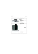
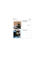
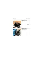
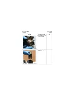
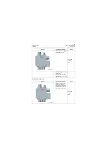
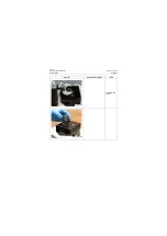
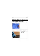
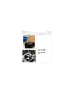
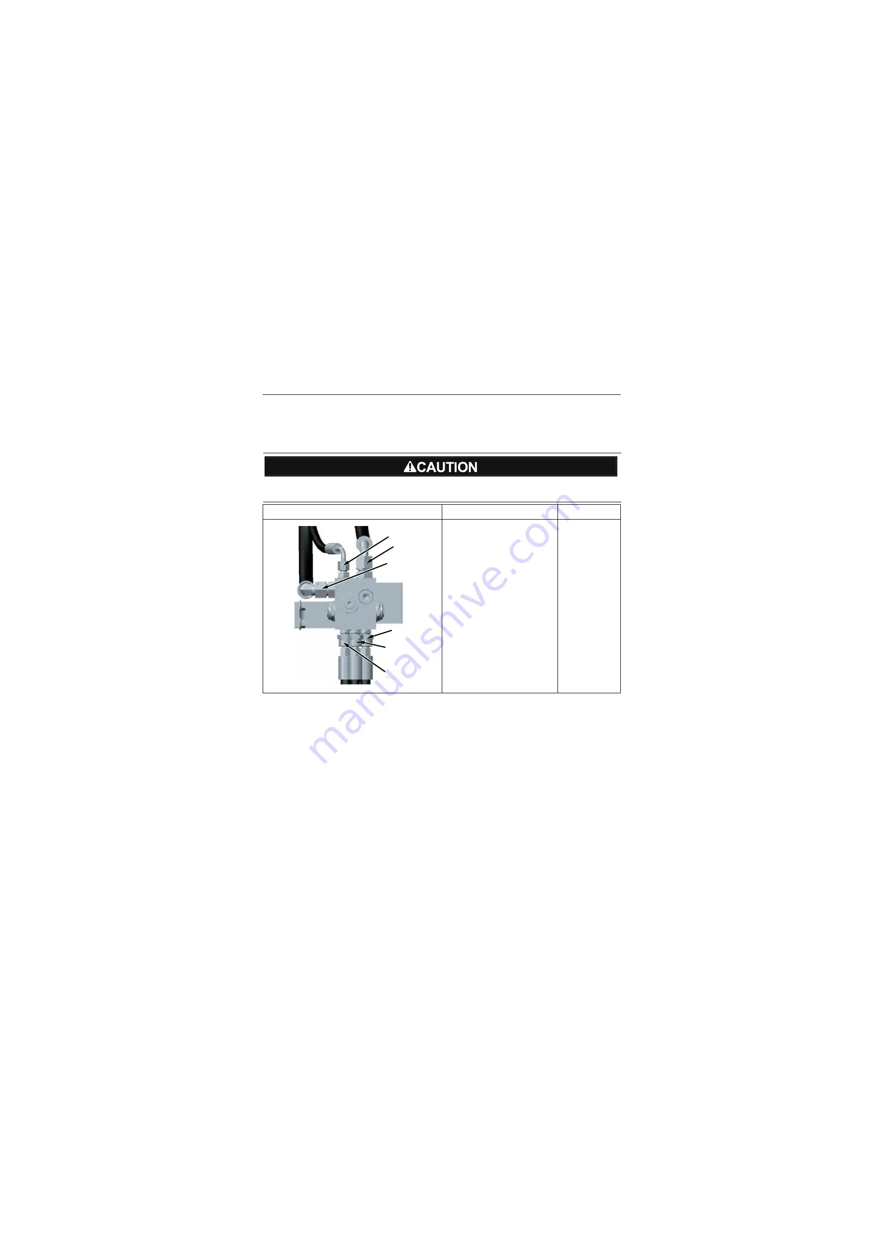
1. Mark 6 hoses connecting
with charge valve respec-
tively as T, P, S, B3, A1, A2
and note that markings shall
be firm;
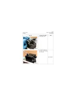
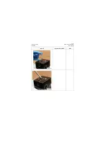
2. Loosen the joints of 5 hoses
and mask the oil ports;
Open-end
wrench: 17, 24,
27mm
P18H00315
T
P
S
A2
B3
A1
Summary of Contents for CLG835H
Page 2: ......
Page 4: ...Contents January 24 2017 CLG835H...
Page 6: ...1 2 General Information January 24 2017 CLG835H...
Page 38: ...1 34 Machine Inspection Table January 24 2017 CLG835H...
Page 156: ...3 2 Power Train System January 24 2017 CLG835H...
Page 214: ...3 2 Power Train System January 24 2017 CLG835H...
Page 272: ...3 60 Testing and adjustment January 24 2017 Power Train Test CLG835H...
Page 276: ...4 4 Hydraulic System January 24 2017 CLG835H...
Page 552: ...6 2 Driver s Cab System January 24 2017 CLG835H...
Page 608: ...7 2 Structure January 24 2017 CLG835H...
Page 662: ...8 4 Electrical System January 24 2017 CLG835H...
Page 677: ...8 19 January 24 2017 Structure Function Principle CLG835H Power System P18E00014...

