4-222
Removal and Installation
January 24, 2017
Brake system
CLG835H
Assembly of cooling pump
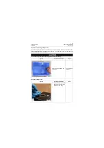
Make sure the connection of hose connector oil port is correct. During disassembly process,
guarantee the cleanliness of pipeline and components and check whether O-ring is aged, dam-
aged and replace timely.
Figures
Operation instruction
Tools
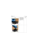
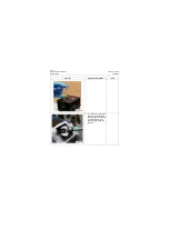
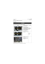
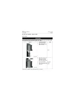
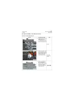
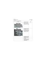
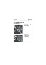
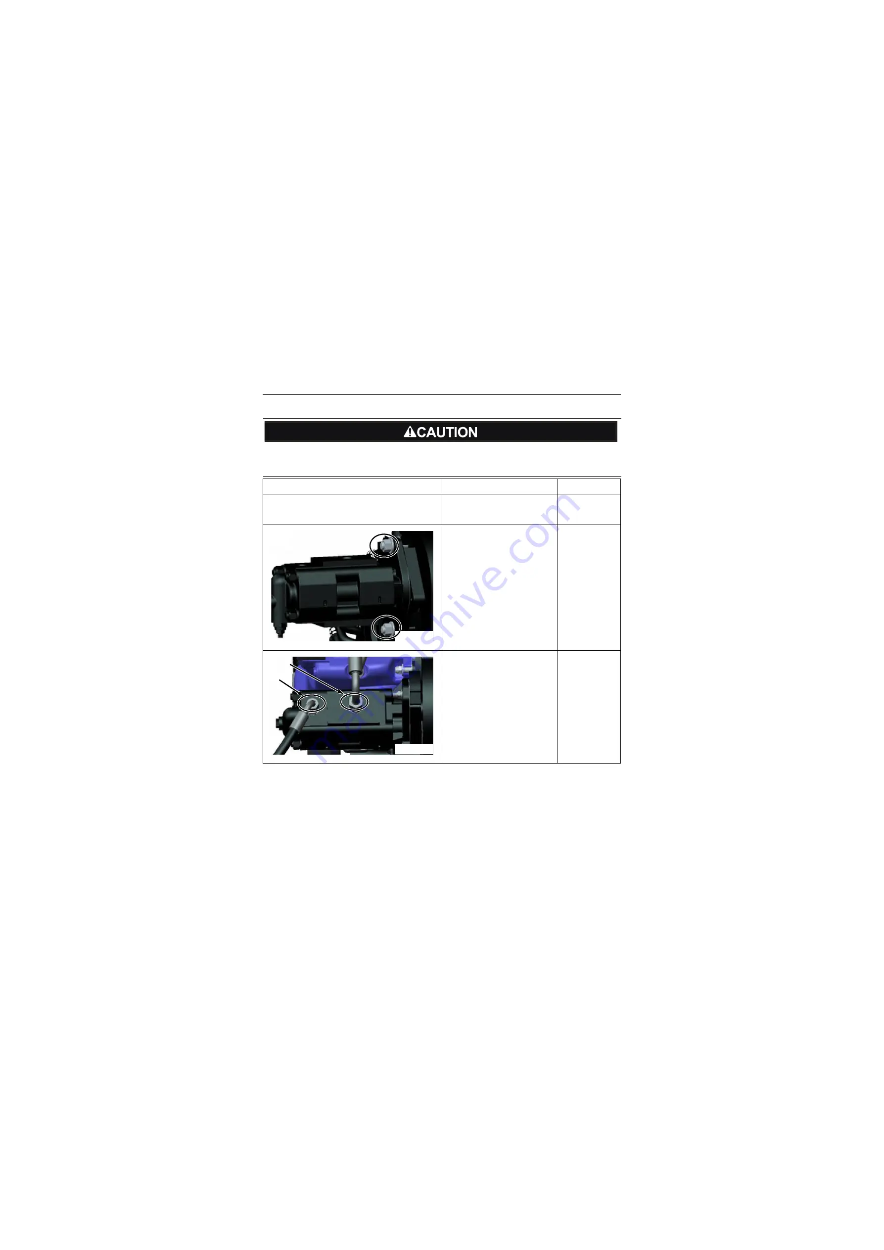
1. Hang the gear pump to the
mounting position with
proper sling;
2. Install gear pump and seal
gasket on gear box;
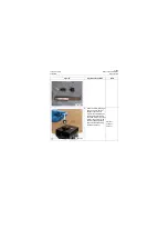
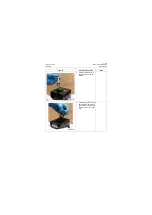
3. Connect the P1 hose with
the tightening torque of hose
joint 89±4Nm\
65.6±2.95lbf·ft
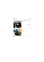
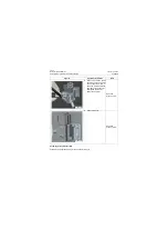
4. Connect the P2 hose with
the tightening torque of hose
joint 47±2Nm\ 34.7±1.5lbf·ft
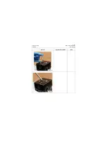
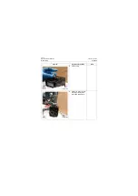
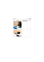
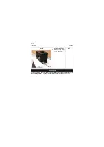
P18H00356
P18H00357
P1
P2
Summary of Contents for CLG835H
Page 2: ......
Page 4: ...Contents January 24 2017 CLG835H...
Page 6: ...1 2 General Information January 24 2017 CLG835H...
Page 38: ...1 34 Machine Inspection Table January 24 2017 CLG835H...
Page 156: ...3 2 Power Train System January 24 2017 CLG835H...
Page 214: ...3 2 Power Train System January 24 2017 CLG835H...
Page 272: ...3 60 Testing and adjustment January 24 2017 Power Train Test CLG835H...
Page 276: ...4 4 Hydraulic System January 24 2017 CLG835H...
Page 552: ...6 2 Driver s Cab System January 24 2017 CLG835H...
Page 608: ...7 2 Structure January 24 2017 CLG835H...
Page 662: ...8 4 Electrical System January 24 2017 CLG835H...
Page 677: ...8 19 January 24 2017 Structure Function Principle CLG835H Power System P18E00014...

