4-228
Removal and Installation
January 24, 2017
Brake system
CLG835H
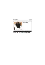
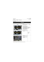
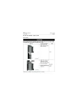
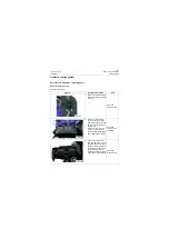
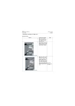
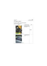
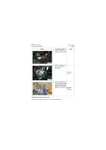
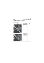
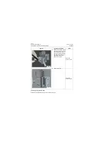
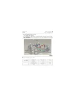
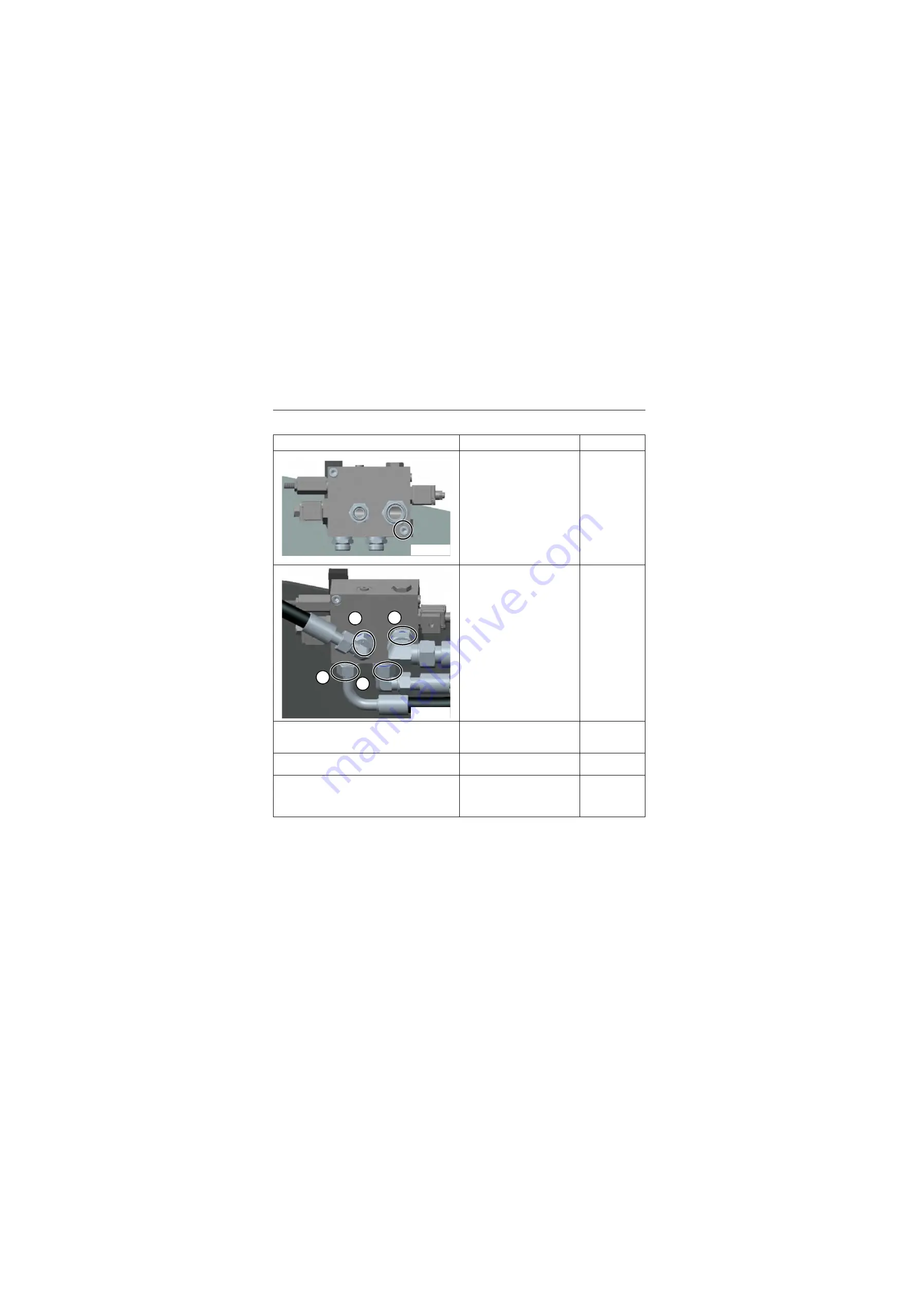
Assembly of solenoid directional valve
Figures
Operation instruction
Tools
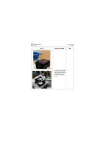
1. Install the solenoid direc-
tional valve to its original
position and tighten 2 bolts
to 52±6Nm\ 38.4
±
4.4lbf
·
ft
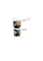
2. Connect the T hose with the
tightening torque of hose
joint 137±6Nm\ 101±4.4lbf·ft
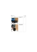
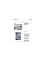
3. 3Connect hoses of B port, A
port and P port and the tight-
ening torque of hose joints is
89±4Nm\ 65.6±3.0lbf·ft
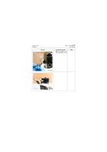
4. Fill the hydraulic oil, start the
machine and idle it for 5min
to bleed the air in the line
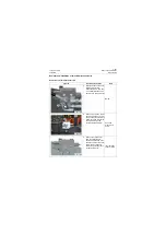
5. Stop the machine and check
it for leakage.
6. Check whether the hydraulic
oil level is normal, and if not,
please fill the hydraulic oil to
the specified level
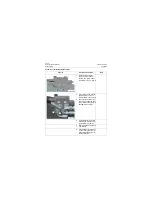
P18H00368
P18H00365
B
P
T
A
Summary of Contents for CLG835H
Page 2: ......
Page 4: ...Contents January 24 2017 CLG835H...
Page 6: ...1 2 General Information January 24 2017 CLG835H...
Page 38: ...1 34 Machine Inspection Table January 24 2017 CLG835H...
Page 156: ...3 2 Power Train System January 24 2017 CLG835H...
Page 214: ...3 2 Power Train System January 24 2017 CLG835H...
Page 272: ...3 60 Testing and adjustment January 24 2017 Power Train Test CLG835H...
Page 276: ...4 4 Hydraulic System January 24 2017 CLG835H...
Page 552: ...6 2 Driver s Cab System January 24 2017 CLG835H...
Page 608: ...7 2 Structure January 24 2017 CLG835H...
Page 662: ...8 4 Electrical System January 24 2017 CLG835H...
Page 677: ...8 19 January 24 2017 Structure Function Principle CLG835H Power System P18E00014...

