


5-14
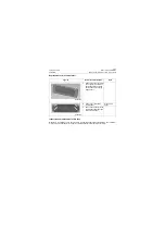
Removal and Installation
January 24, 2017
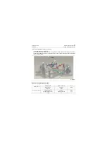
Removal and installation of A/C components
CLG835H
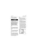
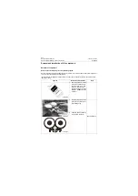
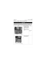
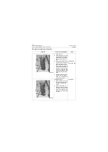
6. Slowly loosen low pressure
valve on manifold gauge so
as to slowly eject refrigerant.
Note the opening of control
valve. Too large flow rate
may easily cause refriger-
ant oil to be ejected out
along with refrigerant. Con-
trol the flow rate to the
extent that no refrigerant oil
is ejected out (released
refrigerant is gaseous, and
refrigerant oil is liquid. Aim
refrigerant outlet at one
piece of white paper, and
observe whether there are
liquid drops to be ejected
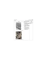
out). After 10 minutes,
slowly open high pressure
valve, and continue control-
ling flow rate to avoid refrig-
erant oil from losing. The
whole release process
should keep 15-30 minutes.
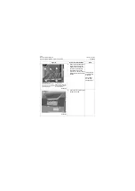
WARNNING: It is forbid-
den to release refrigerant
from high pressure end at the
beginning, since high pres-
sure end is easy to cause
refrigerant oil to be ejected
out along with refrigerant.
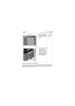
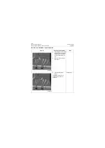
7. Close the high and low pres-
sure connector and remove
it.
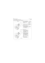
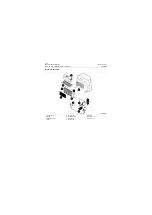
Figures
Removal and installation
Tools
P18A00010
P18A00011
Summary of Contents for CLG835H
Page 2: ......
Page 4: ...Contents January 24 2017 CLG835H...
Page 6: ...1 2 General Information January 24 2017 CLG835H...
Page 38: ...1 34 Machine Inspection Table January 24 2017 CLG835H...
Page 156: ...3 2 Power Train System January 24 2017 CLG835H...
Page 214: ...3 2 Power Train System January 24 2017 CLG835H...
Page 272: ...3 60 Testing and adjustment January 24 2017 Power Train Test CLG835H...
Page 276: ...4 4 Hydraulic System January 24 2017 CLG835H...
Page 552: ...6 2 Driver s Cab System January 24 2017 CLG835H...
Page 608: ...7 2 Structure January 24 2017 CLG835H...
Page 662: ...8 4 Electrical System January 24 2017 CLG835H...
Page 677: ...8 19 January 24 2017 Structure Function Principle CLG835H Power System P18E00014...


