5-23
January 24, 2017
Removal and Installation
CLG835H
Removal and installation of A/C components
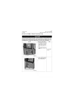
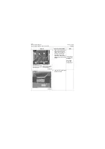
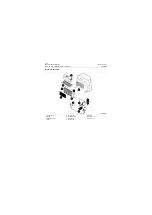
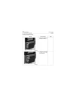
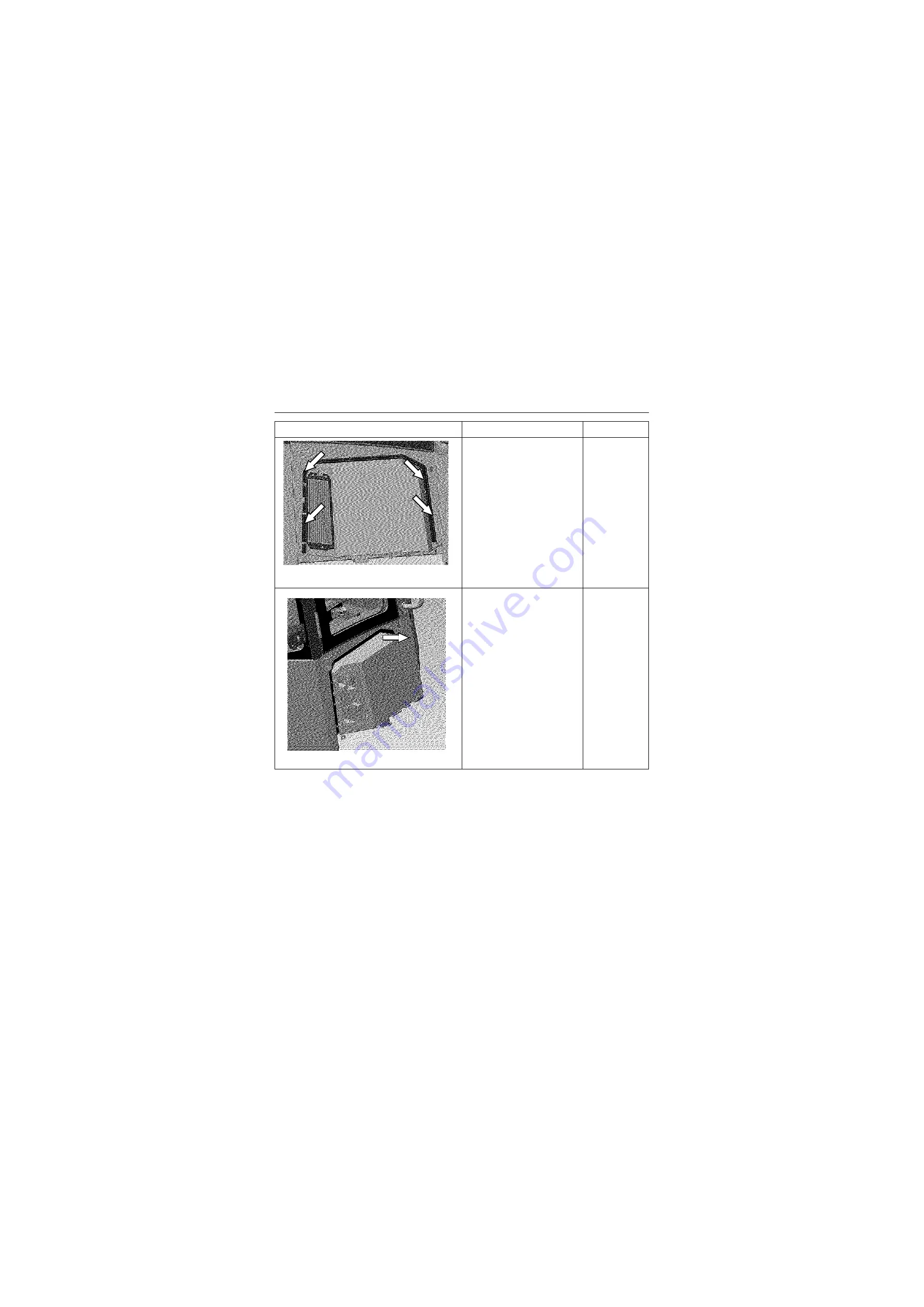
Each lower part location of evaporator assembly
During the actual use, in general, motor, circuit and other faults of evaporator assembly appear. There-
fore, please make an analysis and then disassemble the evaporator according to Fault Diagnosis and
Judgment Fault Diagnosis in this manual. Each lower part location of evaporator assembly will be pro-
vided, so that it is easy to remove and install.
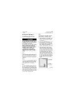
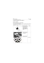
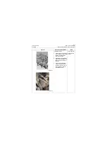
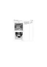
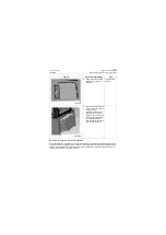
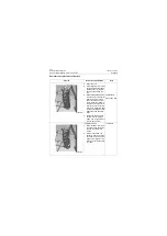
8. Remove the the seal plate
outside the evaporator. (4
M6 bolts)
10# Open-end
wrench
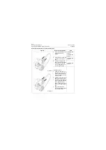
9. Take out the entire evapora-
tor from left to right, and fin-
ish the removal.
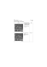
Installation sequence is in
reverse order of removal
sequence. The pipe connec-
tor torque should be based
on the tightening torque
requirements of the respec-
tive A/C pipe connector.
Figures
Removal and installation
Tools
P18A00025
P18A00026
Summary of Contents for CLG835H
Page 2: ......
Page 4: ...Contents January 24 2017 CLG835H...
Page 6: ...1 2 General Information January 24 2017 CLG835H...
Page 38: ...1 34 Machine Inspection Table January 24 2017 CLG835H...
Page 156: ...3 2 Power Train System January 24 2017 CLG835H...
Page 214: ...3 2 Power Train System January 24 2017 CLG835H...
Page 272: ...3 60 Testing and adjustment January 24 2017 Power Train Test CLG835H...
Page 276: ...4 4 Hydraulic System January 24 2017 CLG835H...
Page 552: ...6 2 Driver s Cab System January 24 2017 CLG835H...
Page 608: ...7 2 Structure January 24 2017 CLG835H...
Page 662: ...8 4 Electrical System January 24 2017 CLG835H...
Page 677: ...8 19 January 24 2017 Structure Function Principle CLG835H Power System P18E00014...

