


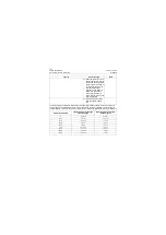


5-42
System Maintenance
January 24, 2017
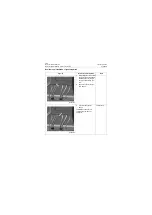
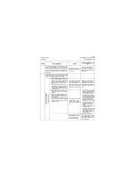
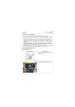
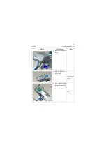
A/C system regular maintenance
CLG835H
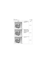
3. Start vacuum pump to vacu-
umize for 5 minutes, and
make sure indications of
high and low pressure
gauges are about -750 mm
Hg (or -0.1 MPa/14.5psi).
Note:
In general, high pressure
gauge and its connector are red,
and low pressure gauge and its
connector are blue.
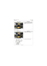
4. First close high pressure
valve (HI) and low pressure
valve (LO) of line pressure
testing device, and then turn
off vacuum pump.
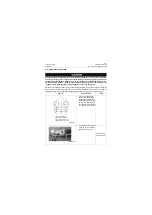
5. Wait for 5 minutes in this
status, and observe that the
reading of low pressure
gauge shall have no
change. The pick up of pres-
sure indicates there is a
leakage in the system.
Check and repair leaking
areas, repeat the 3-5 steps.
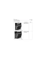
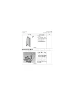
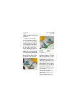
The steps 6-8 below are opera-
tions when portable canned
refrigerant is used. It may
change as the packaging type of
cold media changes. Please
confirm the refrigerant con-
tainer is properly connected to
the manifold gauge.
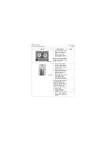
6. Install the plug clock to
refrigerant container.
7. Connect hose connecting
point A of manifold gauge to
the screw plug of refrigerant
container.
Figures
Operation step
Tools
P18A00045
P18A00046
Summary of Contents for CLG835H
Page 2: ......
Page 4: ...Contents January 24 2017 CLG835H...
Page 6: ...1 2 General Information January 24 2017 CLG835H...
Page 38: ...1 34 Machine Inspection Table January 24 2017 CLG835H...
Page 156: ...3 2 Power Train System January 24 2017 CLG835H...
Page 214: ...3 2 Power Train System January 24 2017 CLG835H...
Page 272: ...3 60 Testing and adjustment January 24 2017 Power Train Test CLG835H...
Page 276: ...4 4 Hydraulic System January 24 2017 CLG835H...
Page 552: ...6 2 Driver s Cab System January 24 2017 CLG835H...
Page 608: ...7 2 Structure January 24 2017 CLG835H...
Page 662: ...8 4 Electrical System January 24 2017 CLG835H...
Page 677: ...8 19 January 24 2017 Structure Function Principle CLG835H Power System P18E00014...


