6-19
January 24, 2017
Removal and Installation
CLG835H
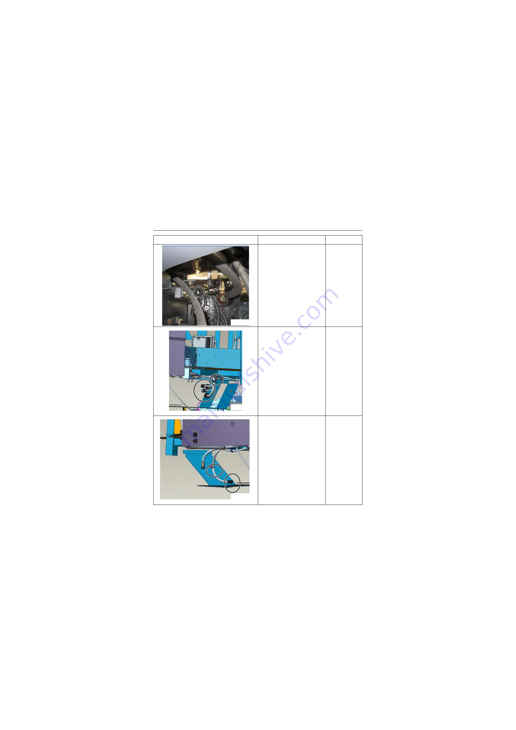
Removal and installation of cab
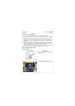
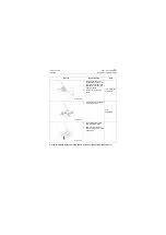
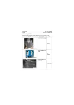
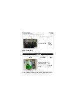
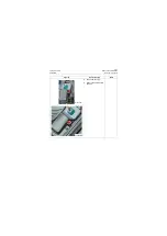
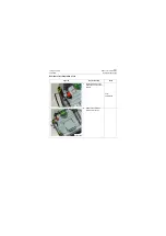
4. Pull out the shift control
solenoid connector on the
transmission-rh.
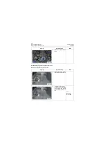
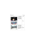
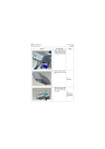
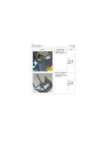
5. Unplug the 4 rear frame har-
ness connectors on the left
mounting bracket of cab and
loosen the fixing ring nut fix-
ing the harness.
Tool:
Open-end
wrench 16#
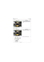
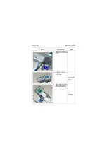
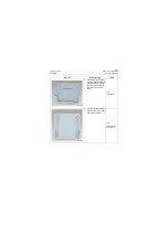
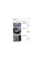
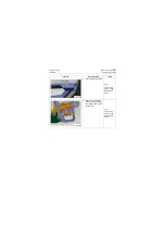
6. Unplug the 1 front frame
harness connectors on the
right mounting bracket of
cab and loosen the fixing
ring nut fixing the harness.
Tool:
Open-end
wrench 16#
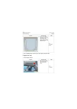
Figures
Operation step
Tools
P18C00035
P18C00036
P18C00037
Summary of Contents for CLG835H
Page 2: ......
Page 4: ...Contents January 24 2017 CLG835H...
Page 6: ...1 2 General Information January 24 2017 CLG835H...
Page 38: ...1 34 Machine Inspection Table January 24 2017 CLG835H...
Page 156: ...3 2 Power Train System January 24 2017 CLG835H...
Page 214: ...3 2 Power Train System January 24 2017 CLG835H...
Page 272: ...3 60 Testing and adjustment January 24 2017 Power Train Test CLG835H...
Page 276: ...4 4 Hydraulic System January 24 2017 CLG835H...
Page 552: ...6 2 Driver s Cab System January 24 2017 CLG835H...
Page 608: ...7 2 Structure January 24 2017 CLG835H...
Page 662: ...8 4 Electrical System January 24 2017 CLG835H...
Page 677: ...8 19 January 24 2017 Structure Function Principle CLG835H Power System P18E00014...

