6-24
Removal and Installation
January 24, 2017
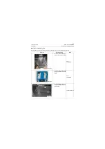
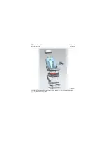
Removal of the seat
CLG835H
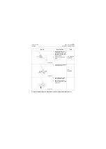
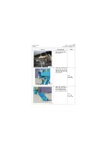
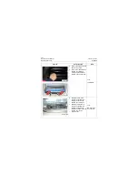
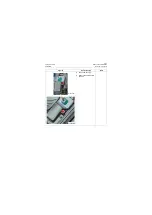
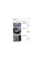
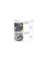
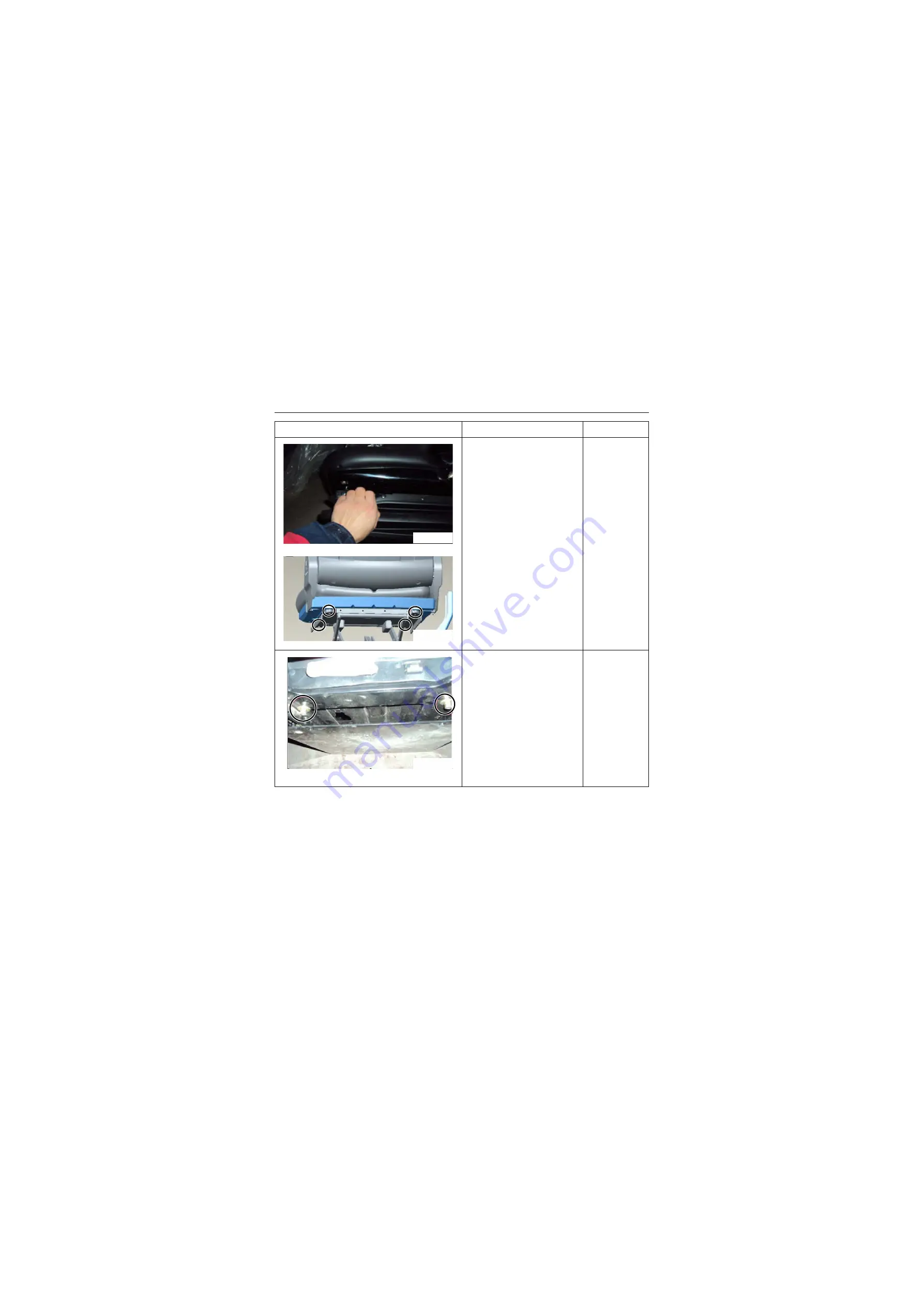
4. Remove the clamp from the
dust cover by hand.
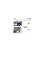
5. Remove four M8 bolts from
shock mount with #13
wrench and the backrest
assembly can be removed.
Tool:
13#Wrench
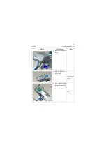
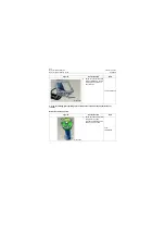
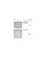
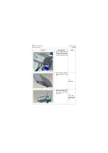
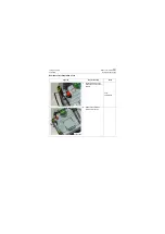
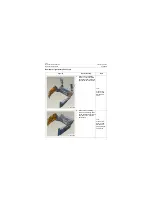
6. Slide the seat forward;
remove the two M8 inner
hexagon bolts from the
shock mount lower part.
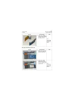
7. Slide the seat rearward;
remove the two M8 inner
hexagon bolts from the
shock mount lower part. The
shock mount can be
removed then.
Tool:
M8 inner hexa-
gon spanner
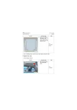
Figures
Operation step
Tools
P18C00044
P18C00045
P18C00046
Summary of Contents for CLG835H
Page 2: ......
Page 4: ...Contents January 24 2017 CLG835H...
Page 6: ...1 2 General Information January 24 2017 CLG835H...
Page 38: ...1 34 Machine Inspection Table January 24 2017 CLG835H...
Page 156: ...3 2 Power Train System January 24 2017 CLG835H...
Page 214: ...3 2 Power Train System January 24 2017 CLG835H...
Page 272: ...3 60 Testing and adjustment January 24 2017 Power Train Test CLG835H...
Page 276: ...4 4 Hydraulic System January 24 2017 CLG835H...
Page 552: ...6 2 Driver s Cab System January 24 2017 CLG835H...
Page 608: ...7 2 Structure January 24 2017 CLG835H...
Page 662: ...8 4 Electrical System January 24 2017 CLG835H...
Page 677: ...8 19 January 24 2017 Structure Function Principle CLG835H Power System P18E00014...


