6-30
Removal and Installation
January 24, 2017
Removal of decoration
CLG835H
Removal of decoration
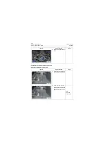
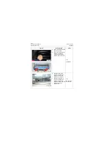
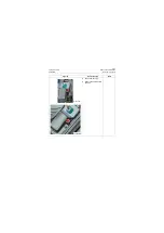
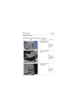
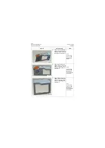
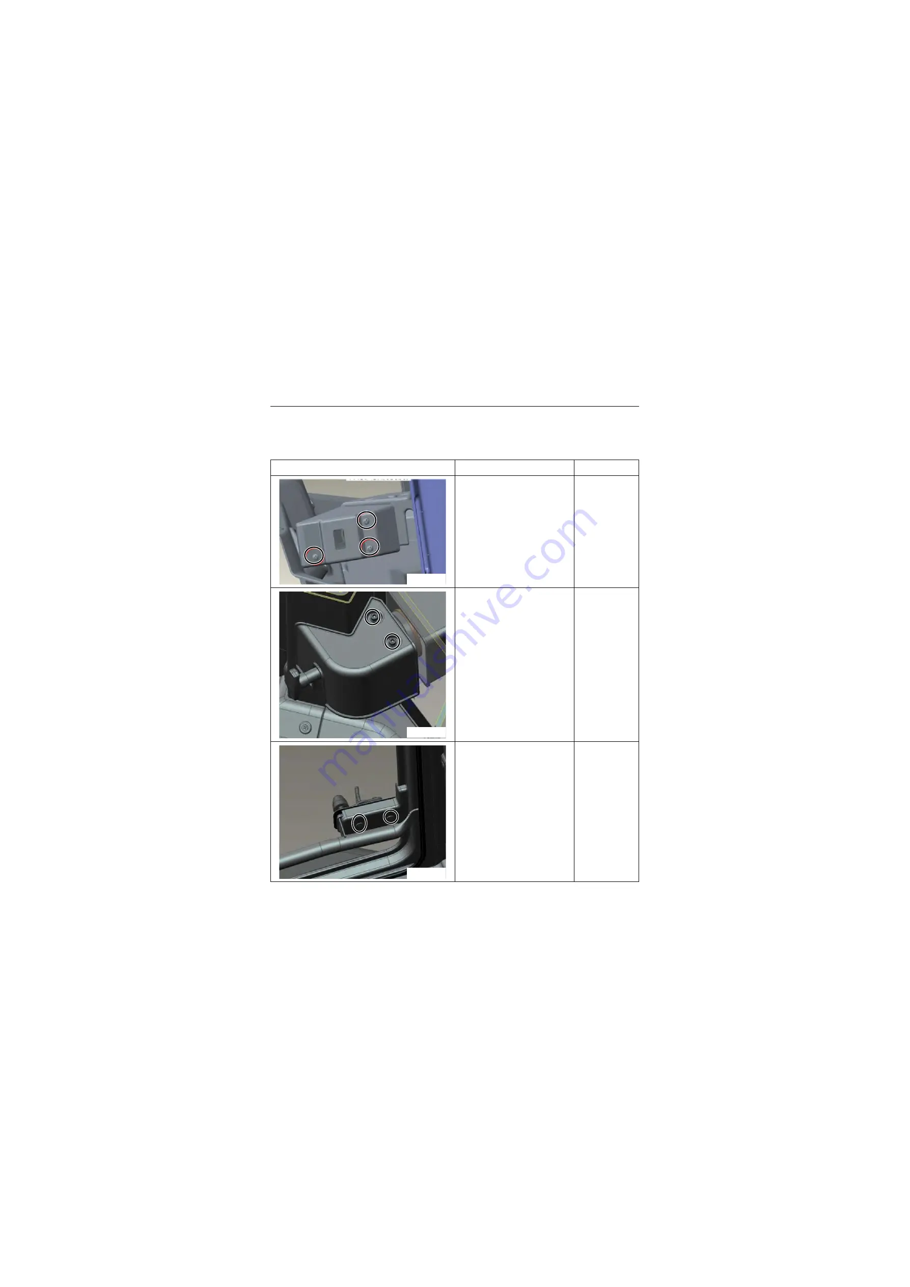
Removal of the rear right positioning lock trim cover in the cab
Figures
Operation step
Tools
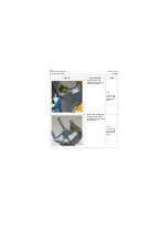
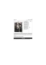
1. Screw out three setscrews
on window-rh fixing lock
cover and remove the cover.
Tool:
Cross-screw-
driver 2 100P
QB/T2564.5-
2002
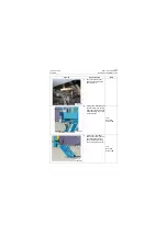
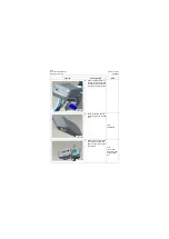
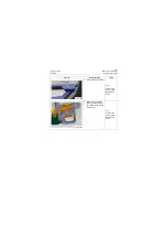
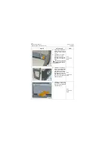
2. Screw out two countersunk
bolts on window-rh position-
ing lock cover.
Tool:
Screwdriver for
countersunk bolt
2 100P QB/
T2564.5-2002
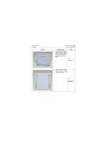
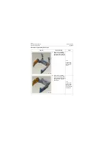
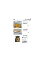
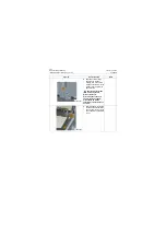
3. Screw out the set inflating
screws on cover and
remove the cover.
Tool:
Cross-screw-
driver 2 100P
QB/T2564.5-
2002
P18C00059
P18C00060
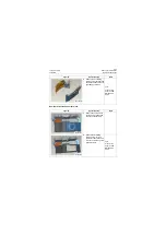
P18C00061
Summary of Contents for CLG835H
Page 2: ......
Page 4: ...Contents January 24 2017 CLG835H...
Page 6: ...1 2 General Information January 24 2017 CLG835H...
Page 38: ...1 34 Machine Inspection Table January 24 2017 CLG835H...
Page 156: ...3 2 Power Train System January 24 2017 CLG835H...
Page 214: ...3 2 Power Train System January 24 2017 CLG835H...
Page 272: ...3 60 Testing and adjustment January 24 2017 Power Train Test CLG835H...
Page 276: ...4 4 Hydraulic System January 24 2017 CLG835H...
Page 552: ...6 2 Driver s Cab System January 24 2017 CLG835H...
Page 608: ...7 2 Structure January 24 2017 CLG835H...
Page 662: ...8 4 Electrical System January 24 2017 CLG835H...
Page 677: ...8 19 January 24 2017 Structure Function Principle CLG835H Power System P18E00014...

