6-42
Removal and Installation
January 24, 2017
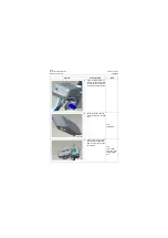
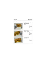
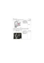
Installation of the left door lock in cab
CLG835H
Figures
Operation step
Tools
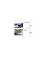
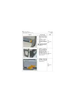
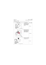
1. Check: check whether the
left door lock parts are com-
plete and in good condition
or not.
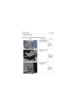
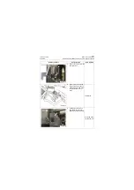
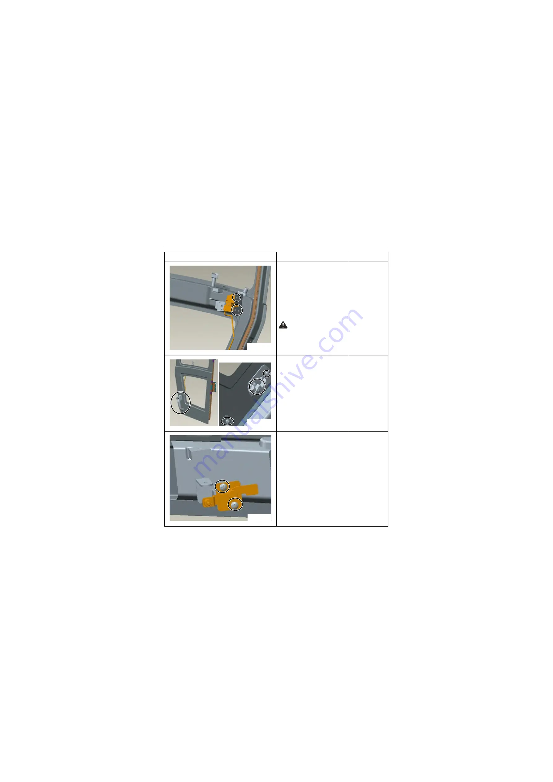
2. Installation of lock block:
Install lock block in the
appropriate location of the
door, and fix it with M6×16
screw.
Caution: The setscrews
must be tightened with-
out looseness.
Tool:
Cross screw-
driver
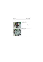
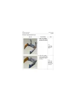
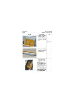
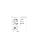
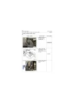
3. Installation of outside han-
dle, mounting plate and pad:
Install outside handle and
mounting plate, pad in the
appropriate location of the
door together, and then fix
them with M6×20 screw. The
setscrews must be tightened
without looseness.
Tool:
Cross screw-
driver
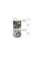
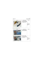
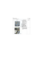
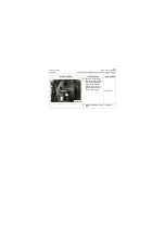
4. Installation of adapter plate:
Fix it with M6×16 screw, and
setscrews must be tightened
without looseness.
Tool:
Cross screw-
driver
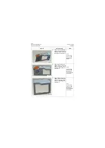
P18C00085
P18C00086
P18C00087
Summary of Contents for CLG835H
Page 2: ......
Page 4: ...Contents January 24 2017 CLG835H...
Page 6: ...1 2 General Information January 24 2017 CLG835H...
Page 38: ...1 34 Machine Inspection Table January 24 2017 CLG835H...
Page 156: ...3 2 Power Train System January 24 2017 CLG835H...
Page 214: ...3 2 Power Train System January 24 2017 CLG835H...
Page 272: ...3 60 Testing and adjustment January 24 2017 Power Train Test CLG835H...
Page 276: ...4 4 Hydraulic System January 24 2017 CLG835H...
Page 552: ...6 2 Driver s Cab System January 24 2017 CLG835H...
Page 608: ...7 2 Structure January 24 2017 CLG835H...
Page 662: ...8 4 Electrical System January 24 2017 CLG835H...
Page 677: ...8 19 January 24 2017 Structure Function Principle CLG835H Power System P18E00014...

