7-12
Removal and Installation
January 24, 2017
Removal and installation of hinge assembly
CLG835H
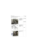
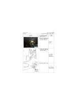
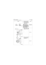
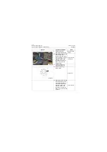
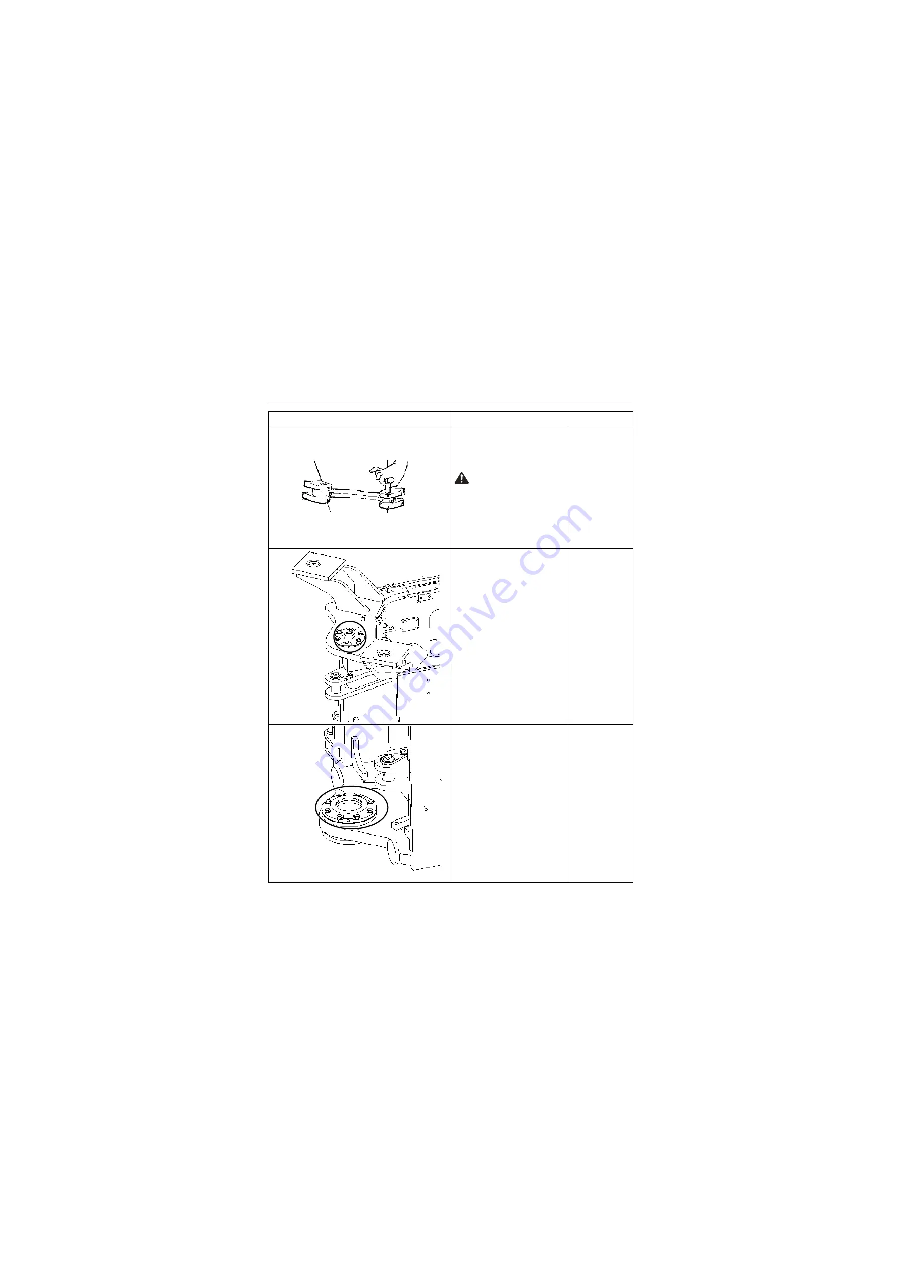
6. Remove steering fixed link,
and lift the front frame out
with lifting equipment and
place on firm ground
CAUTION: The
personnel operating
lifting equipment shall have
relevant qualifications, and
only can operate on the
premise that equipment and
lifting sling are normal and
safety is guaranteed!
Hoisting equip-
ment (over 5ton)
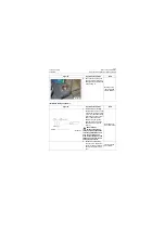
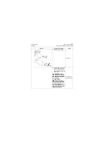
7. Remove 6 captive bolts from
upper hinge and remove the
upper and lower end cover
18# Wrench
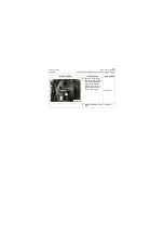
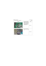
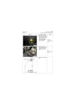
8. Remove eight captive bolts
from lower hinge, and
remove upper cover and
lower end cover
18# Wrench
Figures
Operation instruction
Tools
P18S00013
P18S00014
P18S00015
Summary of Contents for CLG835H
Page 2: ......
Page 4: ...Contents January 24 2017 CLG835H...
Page 6: ...1 2 General Information January 24 2017 CLG835H...
Page 38: ...1 34 Machine Inspection Table January 24 2017 CLG835H...
Page 156: ...3 2 Power Train System January 24 2017 CLG835H...
Page 214: ...3 2 Power Train System January 24 2017 CLG835H...
Page 272: ...3 60 Testing and adjustment January 24 2017 Power Train Test CLG835H...
Page 276: ...4 4 Hydraulic System January 24 2017 CLG835H...
Page 552: ...6 2 Driver s Cab System January 24 2017 CLG835H...
Page 608: ...7 2 Structure January 24 2017 CLG835H...
Page 662: ...8 4 Electrical System January 24 2017 CLG835H...
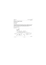
Page 677: ...8 19 January 24 2017 Structure Function Principle CLG835H Power System P18E00014...

