7-15
January 24, 2017
Removal and Installation
CLG835H
Removal and installation of hinge assembly
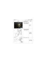
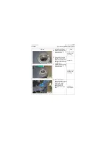
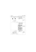
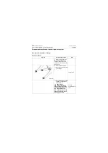
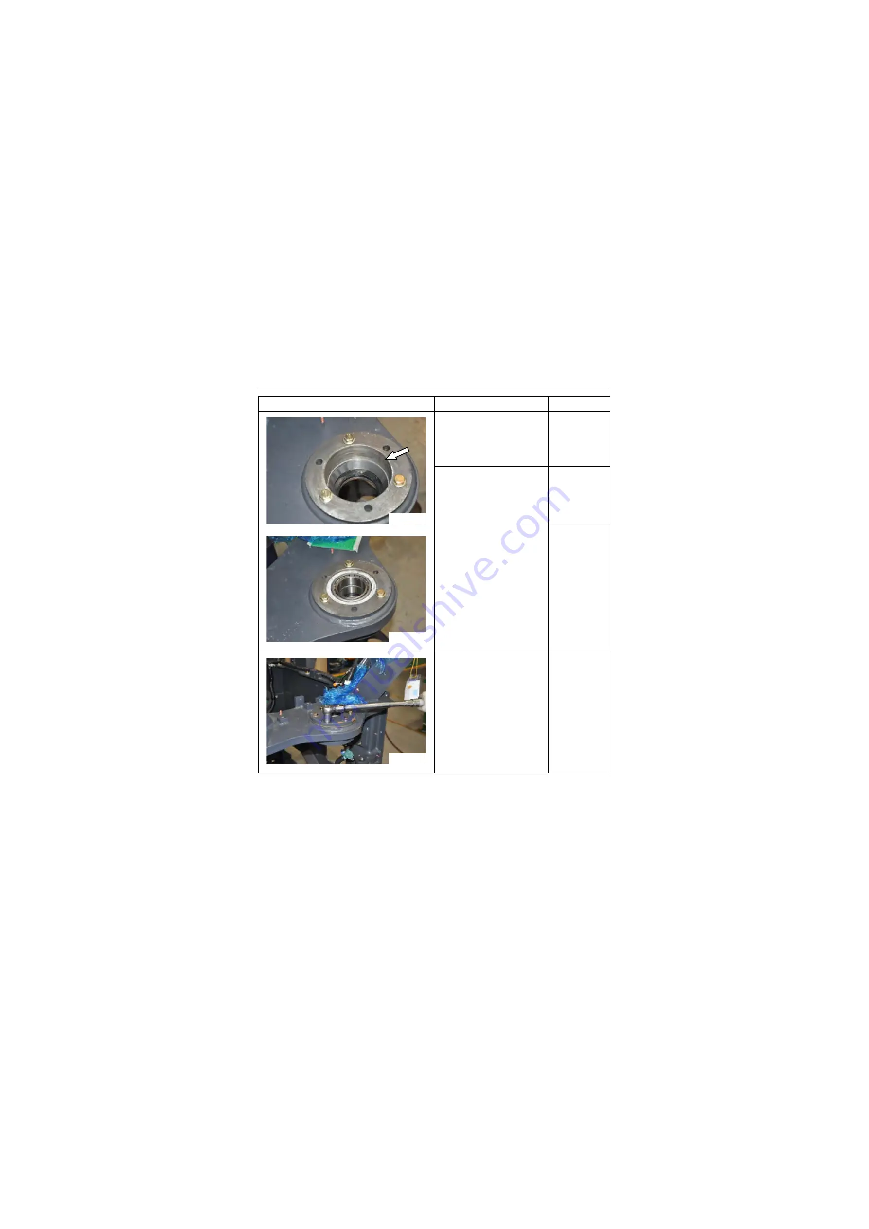
5. Install one frozen tapered
roller bearing cone cup into
lower hinge hole
Copper bar and
bearing knock-
ing tooling
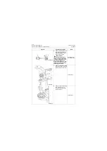
6. Install two tapered roller
bearing cones into lower
hinge holes, and pay atten-
tion that two tapered roller
bearing cones are in oppo-
site directions.
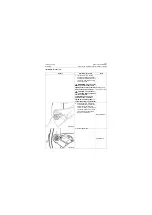
Copper bar
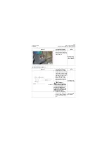
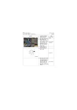
7. Install another frozen taper
roller bearing cone cup into
lower hinge hole.
Copper bar and
bearing knock-
ing tooling
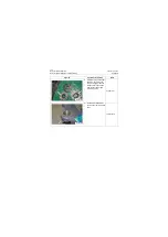
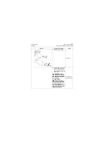
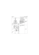
8. Select the shim with
appropriate thickness, install
the shim and upper and
lower covers, tighten
mounting bolts, and
tightening torque is:
120±10N.m/ 88.5±7.375
lbf·ft.
18# Wrench
Torque wrench
Figures
Operation instruction
Tools
P18S00020
P18S00021
P18S00022
Summary of Contents for CLG835H
Page 2: ......
Page 4: ...Contents January 24 2017 CLG835H...
Page 6: ...1 2 General Information January 24 2017 CLG835H...
Page 38: ...1 34 Machine Inspection Table January 24 2017 CLG835H...
Page 156: ...3 2 Power Train System January 24 2017 CLG835H...
Page 214: ...3 2 Power Train System January 24 2017 CLG835H...
Page 272: ...3 60 Testing and adjustment January 24 2017 Power Train Test CLG835H...
Page 276: ...4 4 Hydraulic System January 24 2017 CLG835H...
Page 552: ...6 2 Driver s Cab System January 24 2017 CLG835H...
Page 608: ...7 2 Structure January 24 2017 CLG835H...
Page 662: ...8 4 Electrical System January 24 2017 CLG835H...
Page 677: ...8 19 January 24 2017 Structure Function Principle CLG835H Power System P18E00014...


