7-19
January 24, 2017
Removal and Installation
CLG835H
Removal and installation of hinge assembly
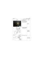
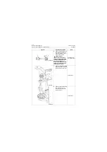
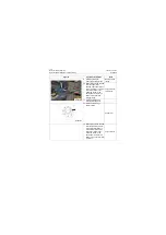
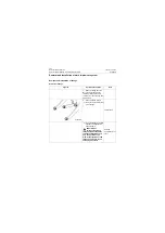
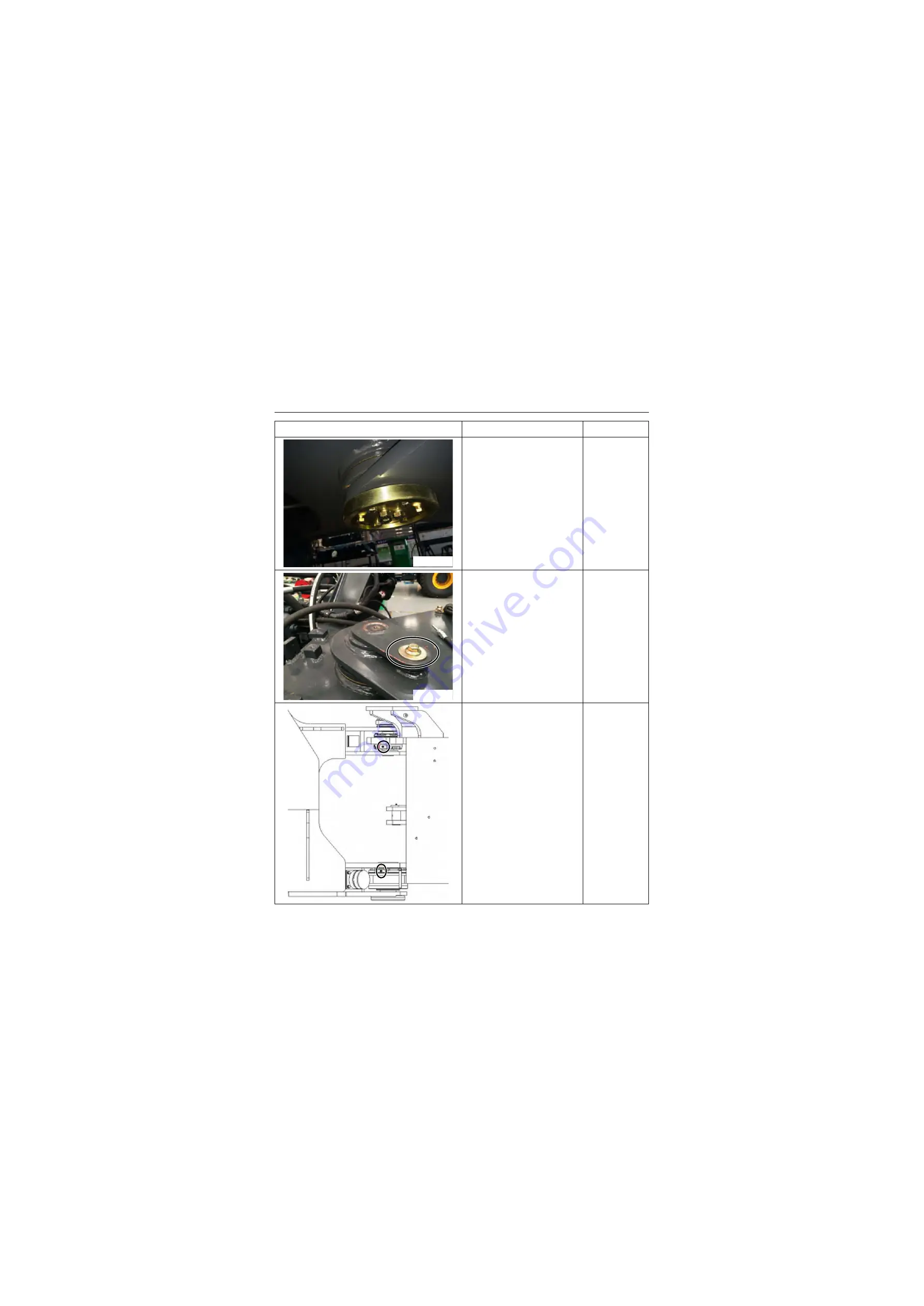
18. Select the shim with appro-
priate thickness, install the
shim and lock plate, tighten
mounting bolts and the
torque of bolts fixing the
hinge pin is 68±14Nm/
50.15±10.325lbf·ft
.
18#, 24#
spanner, torque
spanner
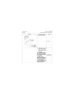
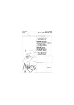
19. Install the upper hinge
cover, tighten mounting bolt,
and tightening torque is:
90±12N.m/ 66.375±8.85
lbf·ft
18#
Wrench,torque
wrench
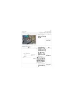
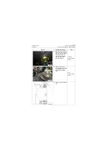
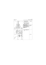
20. Install the joint of lubrication
pipe
Figures
Operation instruction
Tools
P18S00028
P18S00029
P18S00030
Summary of Contents for CLG835H
Page 2: ......
Page 4: ...Contents January 24 2017 CLG835H...
Page 6: ...1 2 General Information January 24 2017 CLG835H...
Page 38: ...1 34 Machine Inspection Table January 24 2017 CLG835H...
Page 156: ...3 2 Power Train System January 24 2017 CLG835H...
Page 214: ...3 2 Power Train System January 24 2017 CLG835H...
Page 272: ...3 60 Testing and adjustment January 24 2017 Power Train Test CLG835H...
Page 276: ...4 4 Hydraulic System January 24 2017 CLG835H...
Page 552: ...6 2 Driver s Cab System January 24 2017 CLG835H...
Page 608: ...7 2 Structure January 24 2017 CLG835H...
Page 662: ...8 4 Electrical System January 24 2017 CLG835H...
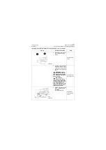
Page 677: ...8 19 January 24 2017 Structure Function Principle CLG835H Power System P18E00014...


