7-48
Removal and Installation
January 24, 2017
Removal and installation of work implement system
CLG835H
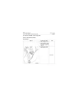
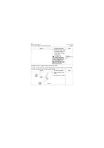
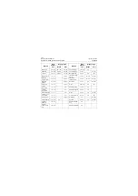
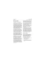
4) Install the captive bolt of
linkage front pin.
18# Wrench
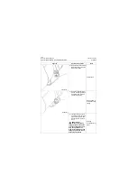
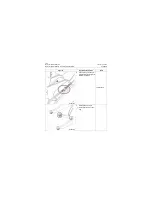
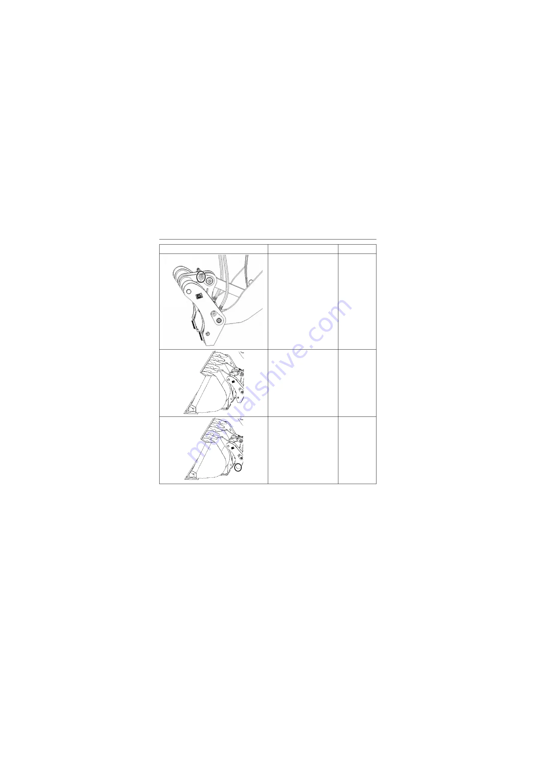
4, Install the quick coupler
bucket
1) Operate the machine, and
align the upper mounting
pin of quick coupler frame
with upper mounting hole of
quick coupler bucket
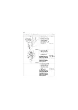
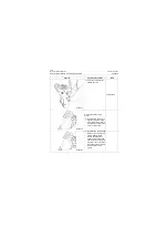
2) Operate the machine, align
the lower pin hole of quick
coupler frame with the
lower mounting hole of
quick coupler bucket, and
operate the third linkage of
pilot lever, then extend the
pin of quick coupler bucket,
lock the quick coupler
bucket.
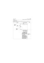
Figures
Operation instruction
Tools
P18S00077
P18S00078
P18S00079
Summary of Contents for CLG835H
Page 2: ......
Page 4: ...Contents January 24 2017 CLG835H...
Page 6: ...1 2 General Information January 24 2017 CLG835H...
Page 38: ...1 34 Machine Inspection Table January 24 2017 CLG835H...
Page 156: ...3 2 Power Train System January 24 2017 CLG835H...
Page 214: ...3 2 Power Train System January 24 2017 CLG835H...
Page 272: ...3 60 Testing and adjustment January 24 2017 Power Train Test CLG835H...
Page 276: ...4 4 Hydraulic System January 24 2017 CLG835H...
Page 552: ...6 2 Driver s Cab System January 24 2017 CLG835H...
Page 608: ...7 2 Structure January 24 2017 CLG835H...
Page 662: ...8 4 Electrical System January 24 2017 CLG835H...
Page 677: ...8 19 January 24 2017 Structure Function Principle CLG835H Power System P18E00014...

