7-49
January 24, 2017
Removal and Installation
CLG835H
Removal and installation of work implement system
Replacement of bucket movable blade, movable tooth and tip
Figures
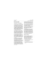
Operation instruction
Tools
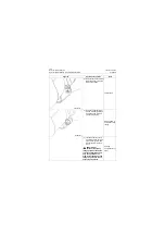
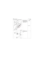
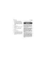
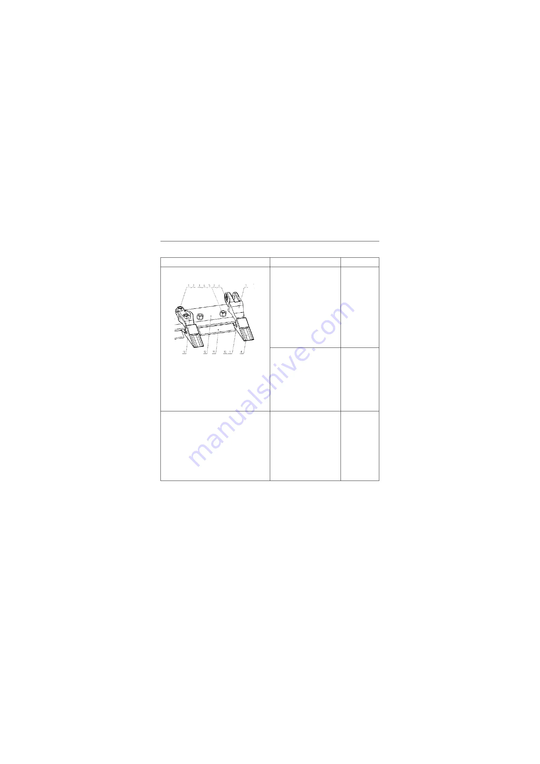
1. Replace the tip:
1) Use hammer and pin
knocking tooling to remove
the pin (9) connecting tip
and tooth.
2) Take out the tip (8) and the
retainer (10).
3) Install new retainer (10) and
tip (8).
(4) Align the tip with tip mount-
ing hole, and install new pin
(9).
Hammer and pin
knocking tooling
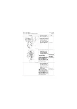
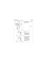
2. Replace the middle tooth of
bucket:
1) Remove the nut (2) and
lock bolt (1) fixing tooth.
2) Take out the tooth (13).
3) Install new tooth (13) on
cutting edge (12).
4) Install new lock bolt (1) and
nut (2).
50# Socket
wrench
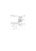
3. Replace the side tooth of
bucket:
1) Remove the nut (2) and
lock bolt (6) fixing side
tooth.
2) Take out the side tooth (7).
3) Install new side tooth (7) on
cutting edge (12).
4) Install new lock bolt (6) and
nut (2).
50# Socket
wrench
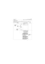
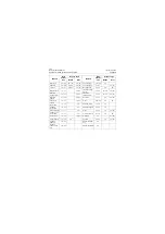
P18S00080
1. Lock bolt
2. Nut
3. Nut
4. Washer
5. Bolt
6. Lock bolt
7. Side gear body
8. Gear sleeve
9. Pin
10.Retainer
11.Movable Blade
12.Cutting edge
13.Gear body
Summary of Contents for CLG835H
Page 2: ......
Page 4: ...Contents January 24 2017 CLG835H...
Page 6: ...1 2 General Information January 24 2017 CLG835H...
Page 38: ...1 34 Machine Inspection Table January 24 2017 CLG835H...
Page 156: ...3 2 Power Train System January 24 2017 CLG835H...
Page 214: ...3 2 Power Train System January 24 2017 CLG835H...
Page 272: ...3 60 Testing and adjustment January 24 2017 Power Train Test CLG835H...
Page 276: ...4 4 Hydraulic System January 24 2017 CLG835H...
Page 552: ...6 2 Driver s Cab System January 24 2017 CLG835H...
Page 608: ...7 2 Structure January 24 2017 CLG835H...
Page 662: ...8 4 Electrical System January 24 2017 CLG835H...
Page 677: ...8 19 January 24 2017 Structure Function Principle CLG835H Power System P18E00014...


