8-22
Structure Function Principle
January 24, 2017
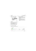
Starting module
CLG835H
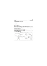
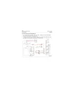
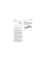
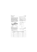
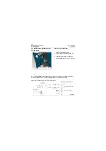
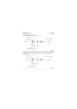
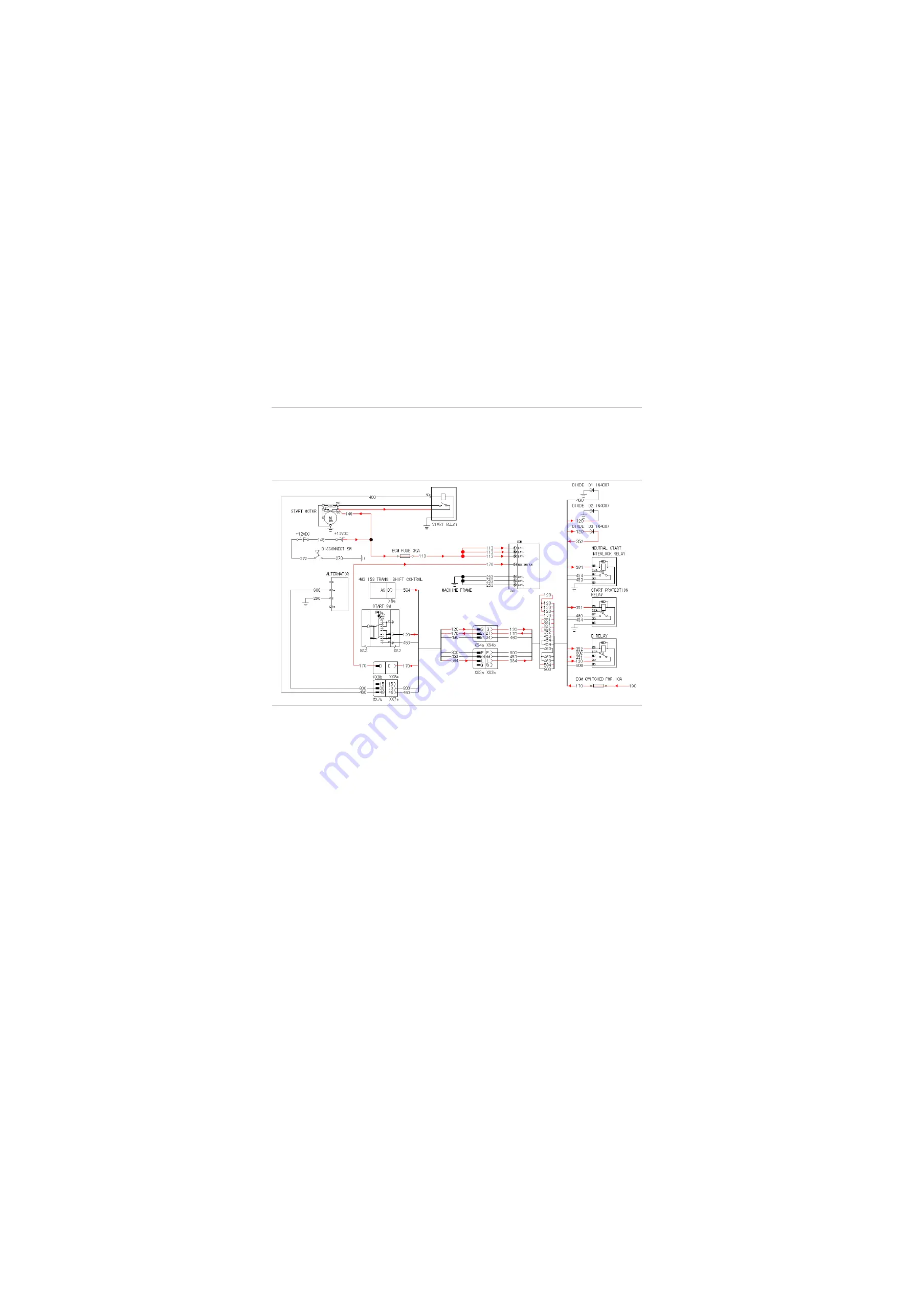
Analysis of the electrical schematic diagram
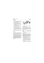
1. Turn on negative switch and switch electric lock to "IGN", the analysis of the schematic diagram
hereof can be found in the power supply system;
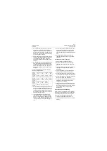
2. Turn the shift control lever to neural position, No.584 wire of the ZF shift controller outputs a high
level signal of (+24V); No.800 wire of engine D+ outputs a low level;
P18E00016
Summary of Contents for CLG835H
Page 2: ......
Page 4: ...Contents January 24 2017 CLG835H...
Page 6: ...1 2 General Information January 24 2017 CLG835H...
Page 38: ...1 34 Machine Inspection Table January 24 2017 CLG835H...
Page 156: ...3 2 Power Train System January 24 2017 CLG835H...
Page 214: ...3 2 Power Train System January 24 2017 CLG835H...
Page 272: ...3 60 Testing and adjustment January 24 2017 Power Train Test CLG835H...
Page 276: ...4 4 Hydraulic System January 24 2017 CLG835H...
Page 552: ...6 2 Driver s Cab System January 24 2017 CLG835H...
Page 608: ...7 2 Structure January 24 2017 CLG835H...
Page 662: ...8 4 Electrical System January 24 2017 CLG835H...
Page 677: ...8 19 January 24 2017 Structure Function Principle CLG835H Power System P18E00014...

