8-41
January 24, 2017
Structure Function Principle
CLG835H
Monitoring system
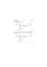
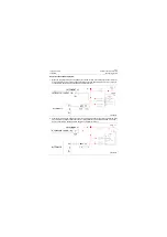
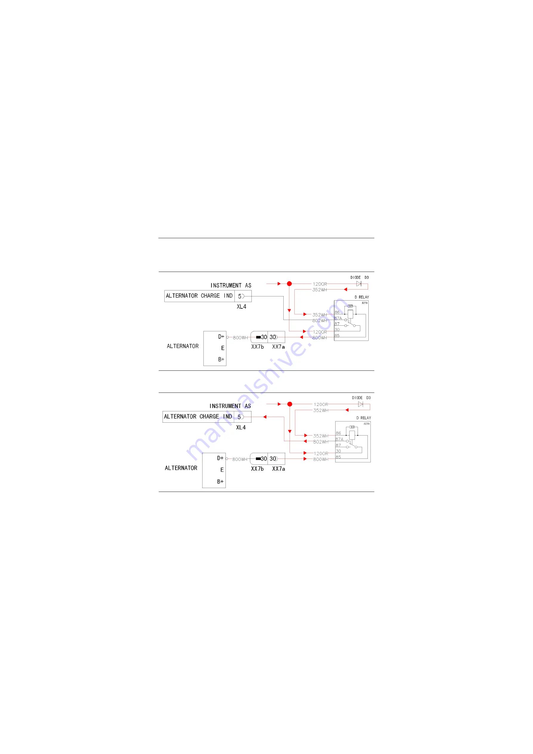
Analysis of the schematic diagram
1. When the complete vehicle is energized but not started, D+ terminal of alternator is under low level,
at which the relay acts due to the voltage difference at the end 85 and 86, pin 30 and 87 of relay is
connected to make No.802 wire suspend and indicator turns on.
2. After entire vehicle starts, if engine is normal, D+ terminal should output high level, at which the relay
stays at normally-closed contact due to "Zero" voltage difference at the end 85 and 86, pin 30 and
87a is connected to make No.802 wire energize and indicator turns off.
P18E00054
P18E00055
Summary of Contents for CLG835H
Page 2: ......
Page 4: ...Contents January 24 2017 CLG835H...
Page 6: ...1 2 General Information January 24 2017 CLG835H...
Page 38: ...1 34 Machine Inspection Table January 24 2017 CLG835H...
Page 156: ...3 2 Power Train System January 24 2017 CLG835H...
Page 214: ...3 2 Power Train System January 24 2017 CLG835H...
Page 272: ...3 60 Testing and adjustment January 24 2017 Power Train Test CLG835H...
Page 276: ...4 4 Hydraulic System January 24 2017 CLG835H...
Page 552: ...6 2 Driver s Cab System January 24 2017 CLG835H...
Page 608: ...7 2 Structure January 24 2017 CLG835H...
Page 662: ...8 4 Electrical System January 24 2017 CLG835H...
Page 677: ...8 19 January 24 2017 Structure Function Principle CLG835H Power System P18E00014...


