8-64
Structure Function Principle
January 24, 2017
Positioner and kickout system
CLG835H
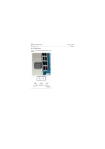
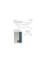
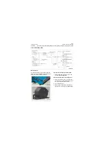
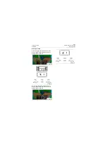
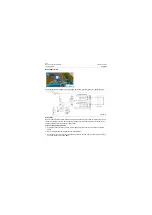
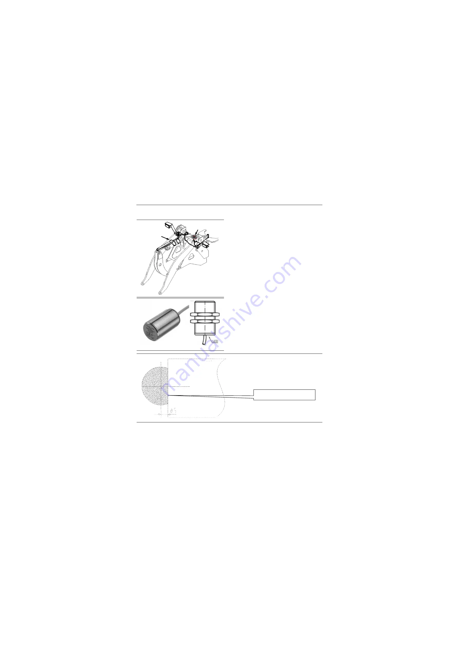
Test on bucket and boom proximity switches
1. Connect the 24V DC power (+) to the termi-
nal at #1 hole of the proximity switch, while
the (-) to the terminal at #2 hole;
2. Turn on the DC power;
3. Draw the metal induction board to the induc-
tive surface of proximity switch, the proximity
distance shall be less than or equal to 12mm,
while the induction area shall be equal or
greater than 2/3;
4. At this moment, the LED at the end of the
switch is lighted up;
5. Turn the digital multimeter to 200V of voltage
position.
6. Connect the black probe to the DC power (-),
while the red probe to the terminal at #3 hole
site of the parking brake switch, thereby, the
value displayed on the DMM shall be 24V.
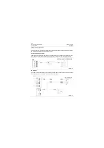
Approach switch
Boom limit
approach switch
Bucket limit
approach switch
P18E00100
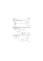
P18E00101
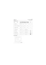
Shaded area is the
effective induction part
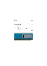
P18E00102
Summary of Contents for CLG835H
Page 2: ......
Page 4: ...Contents January 24 2017 CLG835H...
Page 6: ...1 2 General Information January 24 2017 CLG835H...
Page 38: ...1 34 Machine Inspection Table January 24 2017 CLG835H...
Page 156: ...3 2 Power Train System January 24 2017 CLG835H...
Page 214: ...3 2 Power Train System January 24 2017 CLG835H...
Page 272: ...3 60 Testing and adjustment January 24 2017 Power Train Test CLG835H...
Page 276: ...4 4 Hydraulic System January 24 2017 CLG835H...
Page 552: ...6 2 Driver s Cab System January 24 2017 CLG835H...
Page 608: ...7 2 Structure January 24 2017 CLG835H...
Page 662: ...8 4 Electrical System January 24 2017 CLG835H...
Page 677: ...8 19 January 24 2017 Structure Function Principle CLG835H Power System P18E00014...

