2-58
Removal and Installation
January 24, 2017
Removal and installation of diesel engine
CLG835H
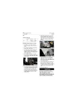
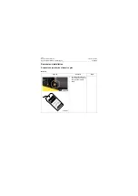
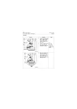
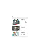
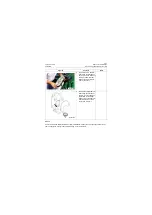
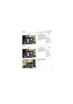
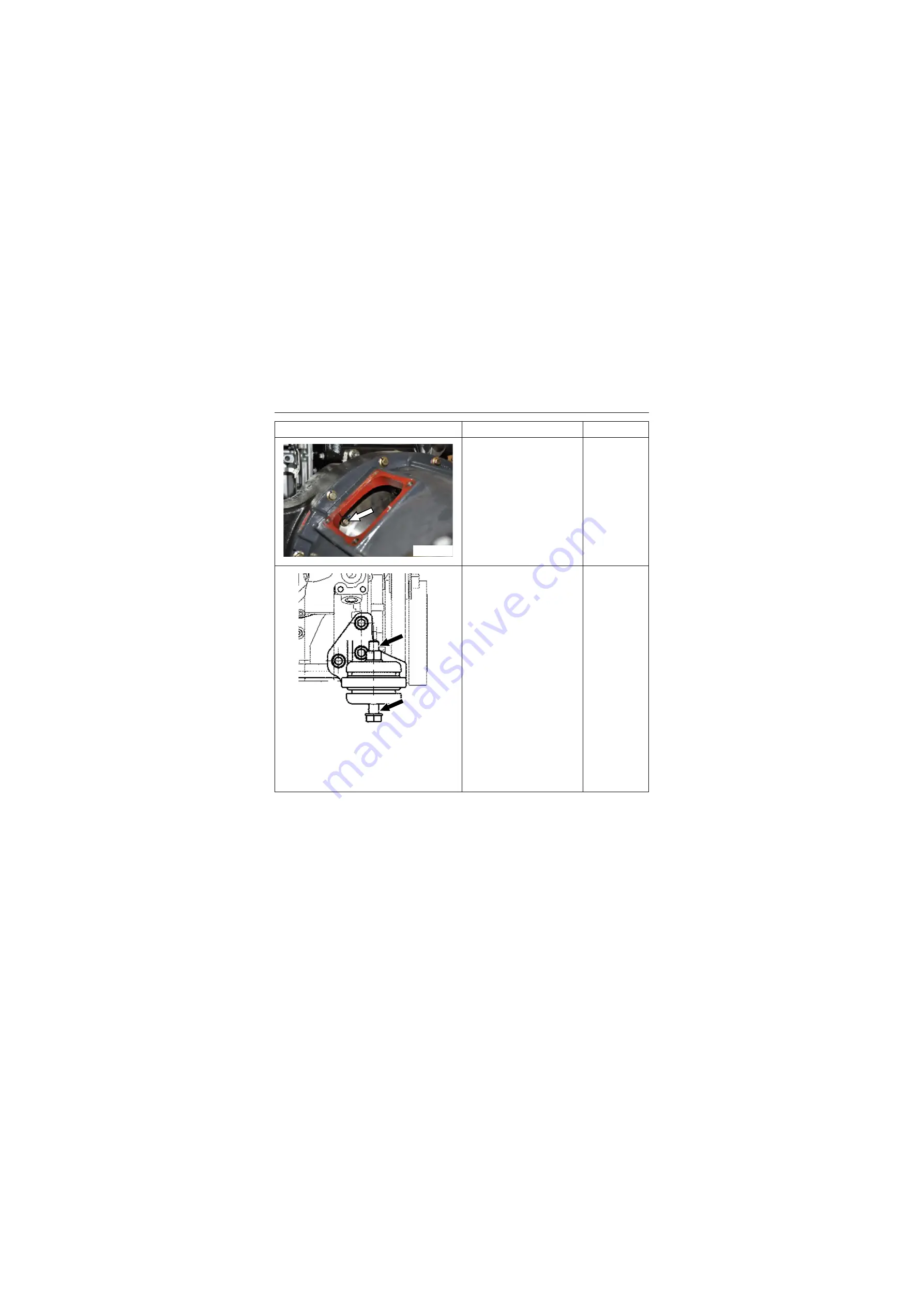
6. Crank the engine flywheel
case to make the torque
converter align with mount-
ing threaded hole on the
engine flywheel, screw and
tighten the fastening bolts
and washer for attaching the
torque converter to the
engine flywheel by hand
with a torque of 60±5Nm
(6±0.5kgf.m).
Tool:
16# Socket,
pneumatic
impact wrench,
open-end 16#
fixed torque
spanner
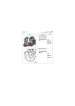
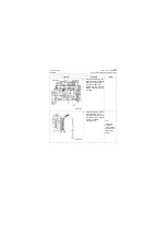
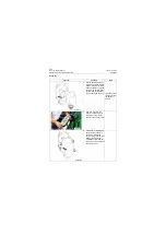
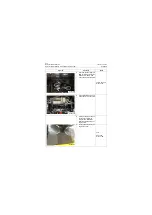
7. Assemble shock absorber,
cap and engine mounting
support together by passing
engine fasteners such as
captive bolt and nut through
them.
Tool:
Open-end
wrench 16#
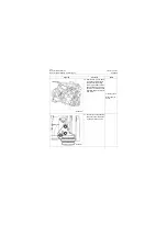
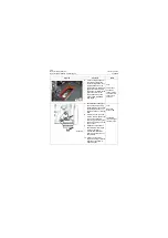
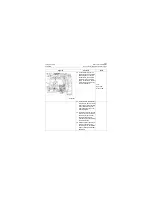
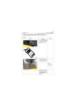
8. Hold nut with an open-end
wrench, and pre-tighten cap-
tive bolt of engine from
under engine mounting sup-
port with a blower gun, a rod
and a socket.
1020±6N.m
(102±0.6 kgf.m)
torque wrench
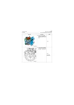
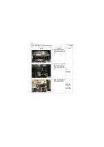
9. Re-tighten captive bolt of
transmission with a torque
wrench according to
removal and installation
requirements and steps of
transmission.
10. Tighten captive bolt of
engine with a torque wrench
to torque of 1020±6N.m
(102±0.6 kgf.m) .
Figures
Contents
Tools
P18P00078
P18P00079
Summary of Contents for CLG835H
Page 2: ......
Page 4: ...Contents January 24 2017 CLG835H...
Page 6: ...1 2 General Information January 24 2017 CLG835H...
Page 38: ...1 34 Machine Inspection Table January 24 2017 CLG835H...
Page 156: ...3 2 Power Train System January 24 2017 CLG835H...
Page 214: ...3 2 Power Train System January 24 2017 CLG835H...
Page 272: ...3 60 Testing and adjustment January 24 2017 Power Train Test CLG835H...
Page 276: ...4 4 Hydraulic System January 24 2017 CLG835H...
Page 552: ...6 2 Driver s Cab System January 24 2017 CLG835H...
Page 608: ...7 2 Structure January 24 2017 CLG835H...
Page 662: ...8 4 Electrical System January 24 2017 CLG835H...
Page 677: ...8 19 January 24 2017 Structure Function Principle CLG835H Power System P18E00014...

