3-46
Removal and Installation
January 24, 2017
Removal and installation of rear axle assembly
CLG835H
Removal and installation of rear axle assembly
Removal of rear axle assembly
Reference picture
Operation step
Tools required
(Remarks)
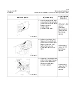
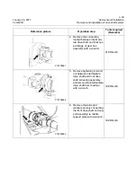
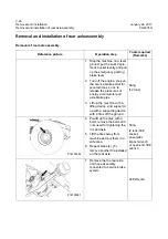
1. Stop the machine on a level
ground, put the work imple-
ment, bucket levelly, and pull
up the emergency parking
brake lever.
2. Turn off the engine, step on
the service brake pedal for
several times, so as to
release the pressures of
energy accumulator and
axle brake pipe.
3. Lift up the machine with a
lifting device, and support it
up with a supporting device
with 4 tires off the ground
Sling
(12 tons)
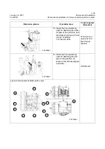
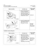
4. Pre-lift up the tires with a
hoist, remove the bolts and
nuts used for tightening the
rim and axle.
5. Lift the tires away from
machine and put them in a
safe area.
6. Repeat steps (4), (5),
remove another tire installed
on the rear axle.
Sling
(2 tons)30#
socket,
pneumatic
impact wrench
or open-end 30#
wrench
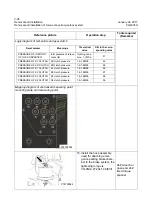
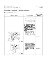
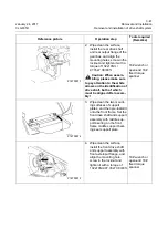
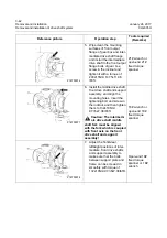
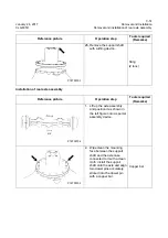
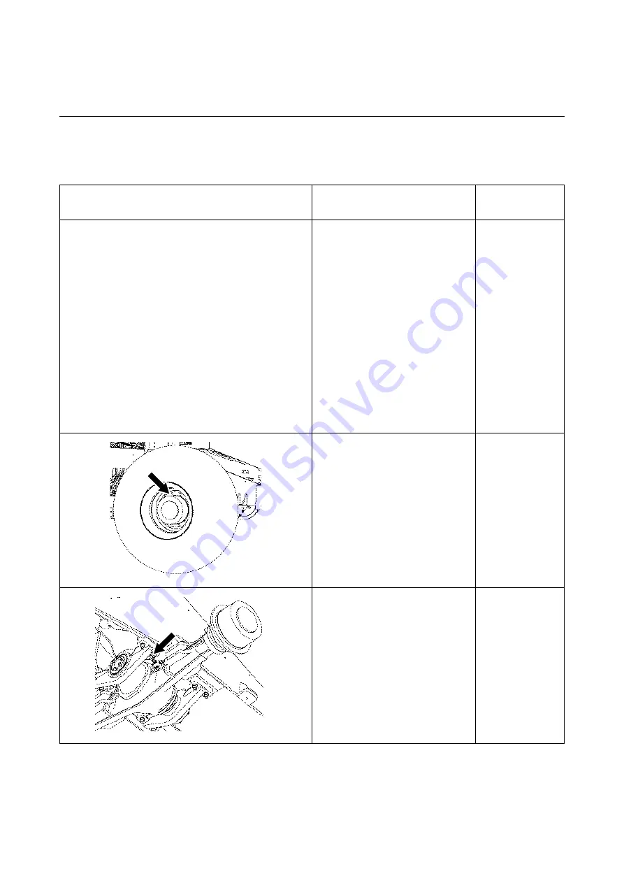
7. Remove the the rear axle
and hose assembly
connected to service brake
system.
24# Wrench
P18T00086
P18T00087
Summary of Contents for CLG835H
Page 2: ......
Page 4: ...Contents January 24 2017 CLG835H...
Page 6: ...1 2 General Information January 24 2017 CLG835H...
Page 38: ...1 34 Machine Inspection Table January 24 2017 CLG835H...
Page 156: ...3 2 Power Train System January 24 2017 CLG835H...
Page 214: ...3 2 Power Train System January 24 2017 CLG835H...
Page 272: ...3 60 Testing and adjustment January 24 2017 Power Train Test CLG835H...
Page 276: ...4 4 Hydraulic System January 24 2017 CLG835H...
Page 552: ...6 2 Driver s Cab System January 24 2017 CLG835H...
Page 608: ...7 2 Structure January 24 2017 CLG835H...
Page 662: ...8 4 Electrical System January 24 2017 CLG835H...
Page 677: ...8 19 January 24 2017 Structure Function Principle CLG835H Power System P18E00014...


