3-56
Removal and Installation
January 24, 2017
Disassembly and assembly of the drive axle
CLG835H
Disassembly and assembly of the drive axle
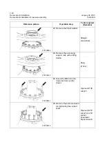
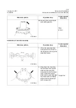
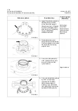
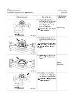
For disassembly and assembly of the drive axle in this machine, see "835H Drive Axle Service Manual"
for details.
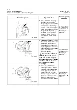
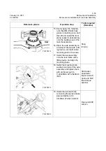
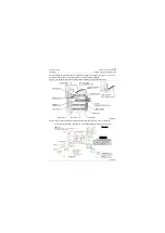
20. Lift up the tire with a hoist
and install it onto the axle,
and then install the rim nut
and tighten it to 600±60Nm\
442.5±44.25 lbf•ft.
30# socket,
pneumatic
impact wrench
or open-end 30#
fixed torque
spanner
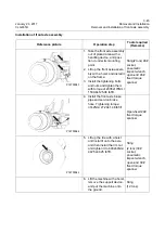
21. Install the steel pipe con-
necting the centralized lubri-
cating system and axle.
Open-end 16#
wrench
22. Lift the machine with a hoist,
remove the support device,
and put the machine onto
the ground.
Sling
(12 tons)
Reference picture
Operation step
Tools required
(Remarks)
P18T00121
P18T00122
Summary of Contents for CLG835H
Page 2: ......
Page 4: ...Contents January 24 2017 CLG835H...
Page 6: ...1 2 General Information January 24 2017 CLG835H...
Page 38: ...1 34 Machine Inspection Table January 24 2017 CLG835H...
Page 156: ...3 2 Power Train System January 24 2017 CLG835H...
Page 214: ...3 2 Power Train System January 24 2017 CLG835H...
Page 272: ...3 60 Testing and adjustment January 24 2017 Power Train Test CLG835H...
Page 276: ...4 4 Hydraulic System January 24 2017 CLG835H...
Page 552: ...6 2 Driver s Cab System January 24 2017 CLG835H...
Page 608: ...7 2 Structure January 24 2017 CLG835H...
Page 662: ...8 4 Electrical System January 24 2017 CLG835H...
Page 677: ...8 19 January 24 2017 Structure Function Principle CLG835H Power System P18E00014...

