4-19
January 24, 2017
Structure Function Principle
CLG835H
Work hydraulic system
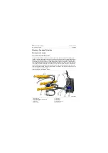
1. When there is no action in the work hydraulic
system, i.e. boom reversing valve and bucket
reversing valve in the control valve are in
neutral position, and variable plunger pump
is at minimum displacement position, the
variable pump hardly has oil to output (only
the minimum displacement required to keep
self-running), oil passages of the control
valve connected to both of big and small cav-
ities of the boom cylinder and bucket cylinder
are sealed, and boom and bucket are kept in
original position.
2. Operate the boom reversing valve controlled
by the pilot valve to lift, lower or float the
boom and manipulate the bucket tilting
reversing valve controlled by the pilot valve to
tilt the bucket forward or backward. There is
an automatic leveling device of bucket
installed on bucket hydraulic cylinder.
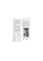
3. Big and small cavities double-acting safety
valves are installed in oil lines of the control
valve connected with big and small cavities of
the bucket cylinder to protect the big and
small cavities of the bucket cylinder from
overload and fill oil and play the role of stabi-
lizing system work and protecting the rele-
vant elements of the system.
B: Technical parameters of work system
Hydraulic oil tank
Installation position and functional structure
The hydraulic oil tank is side-sited type, which is
located on the rear frame in the middle of a
machine, the right side of a cab. The main
function is to store the hydraulic oil required for
work cycle of the hydraulic system and
precipitate the pollutant of oil in hydraulic tank,
separate the air from oil and cool the hydraulic
oil. A return oil filter has been set in the oil tank to
filter the pollutant in oil lines of the hydraulic
system so as to guarantee the cleanliness of
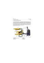
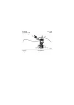
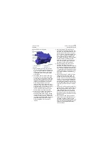
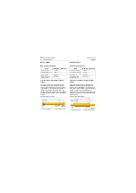
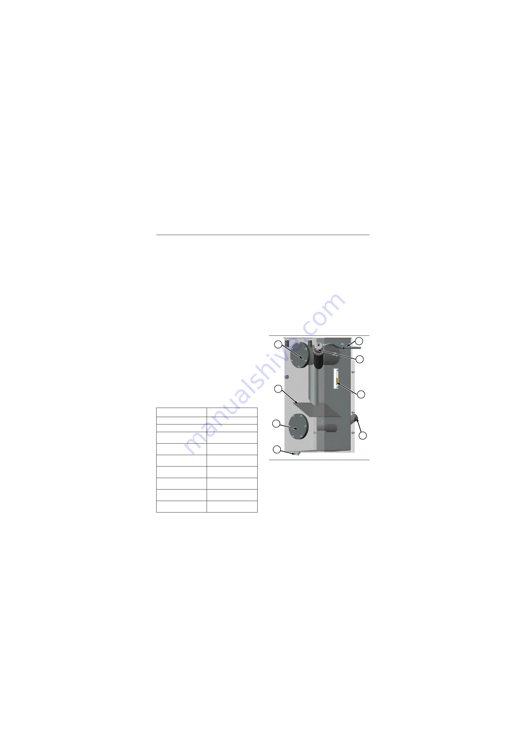
hydraulic oil. Structural diagram of hydraulic oil
tank is as follows:
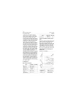
Items
Parameters
System pressure
19±0.3Mpa\2755±43.5psi
System flow
210L/min@2200r/min
Pressure of overload
valve at A1 port
23±0.3MPa\3335±43.5psi
Pressure of overload
valve at B1 port
23±0.3MPa\3335±43.5psi
Pressure of overload
valve at A2 port
23±0.3MPa\3335±43.5psi
Pressure of overload
valve at B2 port
23±0.3MPa\3335±43.5psi
Pressure of overload
valve at A3 port
23±0.3MPa\3335±43.5psi
Pressure of overload
valve at B3 port
23±0.3MPa\3335±43.5psi
Pressure of main safety
valve
21±0.3MPa\3045±43.5psi
Structural diagram of hydraulic oil tank
1. Oil return chamber
and oil return filter
2. Baffle
3. Washing port
4. Oil drain hole
5. Ventilated oil conduit
6. Oil filler, oil filter element and
breather
7. Sight glass
8. Oil suction port
P18H00010
·
1
2
3
4
5
6
7
8
Summary of Contents for CLG835H
Page 2: ......
Page 4: ...Contents January 24 2017 CLG835H...
Page 6: ...1 2 General Information January 24 2017 CLG835H...
Page 38: ...1 34 Machine Inspection Table January 24 2017 CLG835H...
Page 156: ...3 2 Power Train System January 24 2017 CLG835H...
Page 214: ...3 2 Power Train System January 24 2017 CLG835H...
Page 272: ...3 60 Testing and adjustment January 24 2017 Power Train Test CLG835H...
Page 276: ...4 4 Hydraulic System January 24 2017 CLG835H...
Page 552: ...6 2 Driver s Cab System January 24 2017 CLG835H...
Page 608: ...7 2 Structure January 24 2017 CLG835H...
Page 662: ...8 4 Electrical System January 24 2017 CLG835H...
Page 677: ...8 19 January 24 2017 Structure Function Principle CLG835H Power System P18E00014...

