4-35
January 24, 2017
Structure Function Principle
CLG835H
Work hydraulic system
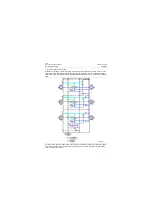
If load of boom is higher than that of bucket, the
signal of high load pressure, detected from the
pressure compensation valve 7, acts on its left
side of spool to make 7 works in the left position,
high load signal leads to reduction of the
compensation valve 7 opening and improvement
of the throttling effect so that the pressure behind
orifice of the bucket valve rod (i.e. in front of
pressure compensation valve 7) is equal to that
of the boom union, meanwhile, as the pressure
in front of unions valve rod is same (the pressure
difference in front of unions valve rod is the same
as that behind), flow of unions is only in relation
to the valve rod opening other than their loads.
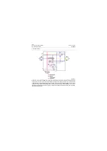
8. Multi-functional way
The multi-functional way is generally used for
realizing actions of quick coupler cylinder, fork
cylinder, side dump cylinder and other multi-
functional attachments. Its principle is the same
as that of the bucket.
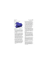
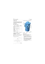
Pilot valve
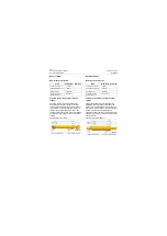
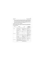
Main technical parameters
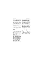
Structure and working principle of pilot valve
The pilot valve shall be installed on the handrail
assembly in the cab and its position can be
adjusted forwards and backwards with the
handrail assembly. The standard configuration of
the model is triplex pilot valve (boom and bucket
way are hydraulically controlled and multi-
functional way is electrically controlled), which
consists of boom operating way, bucket
operating way and multi-functional way. The
boom operating way includes two metering valve
groups, which are respectively used for raise,
lowering and floating lowering of the boom. The
bucket tilting operating way includes two
metering valve groups, which are respectively
used for bucket tilting back and dumping of the
bucket. Multi-functional operating way includes
two metering valve groups, which can be used to
realize actions of multi-functional cylinder, for
example, quick coupler, grapple device and other
attachments. With controlling the handle of pilot
operating valve, the action of each valve group in
boom operating way, bucket operating way and
multi-functional way can be controlled. In
addition, in all metering valves, the displacement
of the spool is in proportional relation with the
operating angle displacement of the handle. The
larger the operating angle of the handle is, the
faster the action speed of the work implement is.
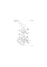
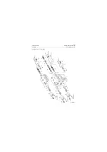
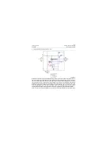
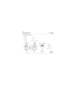
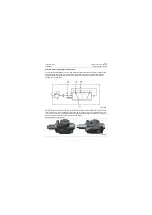
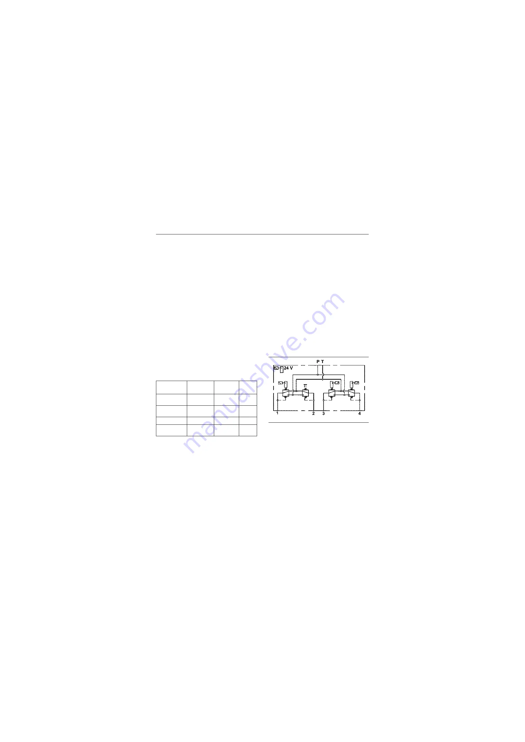
Schematic diagram and outline diagram of pilot
valve are as follows:
Items
Parameters
Service
conditions
Remarks
Working
pressure (MPa)
3.5\507.5
/
/
Maximum
pressure (MPa)
5.0\725
/
/
Flow (L/min)
16\4.23
/
/
Operating fluid
Anti-wear
hydraulic oil
HM46/HV46
/
Schematic diagram of pilot valve
P18H00026
Summary of Contents for CLG835H
Page 2: ......
Page 4: ...Contents January 24 2017 CLG835H...
Page 6: ...1 2 General Information January 24 2017 CLG835H...
Page 38: ...1 34 Machine Inspection Table January 24 2017 CLG835H...
Page 156: ...3 2 Power Train System January 24 2017 CLG835H...
Page 214: ...3 2 Power Train System January 24 2017 CLG835H...
Page 272: ...3 60 Testing and adjustment January 24 2017 Power Train Test CLG835H...
Page 276: ...4 4 Hydraulic System January 24 2017 CLG835H...
Page 552: ...6 2 Driver s Cab System January 24 2017 CLG835H...
Page 608: ...7 2 Structure January 24 2017 CLG835H...
Page 662: ...8 4 Electrical System January 24 2017 CLG835H...
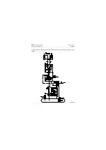
Page 677: ...8 19 January 24 2017 Structure Function Principle CLG835H Power System P18E00014...

