4-110
Removal and Installation
January 24, 2017
Work hydraulic system
CLG835H
Removal and installation of the plunger pump
Removal of the plunger pump
Removal steps:
Figures
Operation instruction
Tools
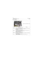
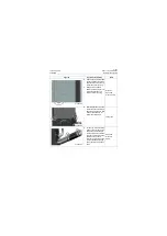
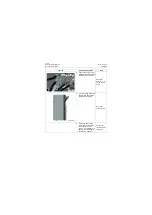
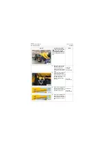
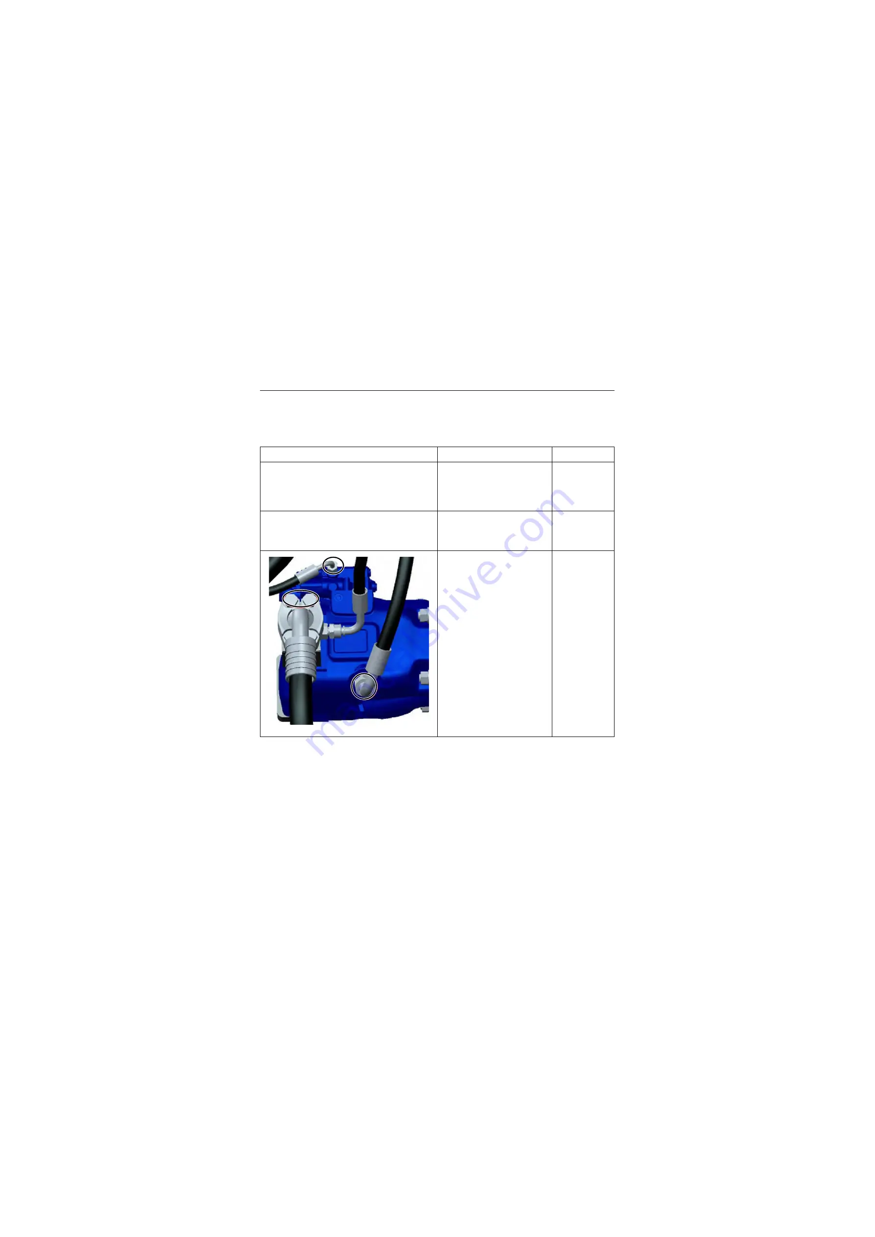
1. Remove the driver seat and
the access port plate of the
bottom plate to expose the
access port at the bottom of
the driver seat;
2. Refer to the steps 3, 4 in
Installation Position and
Functional Structure for
draining the hydraulic oil;
3. Remove the hose assem-
bly, plate, check valve from
the plunger pump opening
and then mask the oil ports;
Open-end
wrench: 17, 21,
32mm
P18H00129
Summary of Contents for CLG835H
Page 2: ......
Page 4: ...Contents January 24 2017 CLG835H...
Page 6: ...1 2 General Information January 24 2017 CLG835H...
Page 38: ...1 34 Machine Inspection Table January 24 2017 CLG835H...
Page 156: ...3 2 Power Train System January 24 2017 CLG835H...
Page 214: ...3 2 Power Train System January 24 2017 CLG835H...
Page 272: ...3 60 Testing and adjustment January 24 2017 Power Train Test CLG835H...
Page 276: ...4 4 Hydraulic System January 24 2017 CLG835H...
Page 552: ...6 2 Driver s Cab System January 24 2017 CLG835H...
Page 608: ...7 2 Structure January 24 2017 CLG835H...
Page 662: ...8 4 Electrical System January 24 2017 CLG835H...
Page 677: ...8 19 January 24 2017 Structure Function Principle CLG835H Power System P18E00014...

