4-220
Removal and Installation
January 24, 2017
Brake system
CLG835H
Removal and installation of brake cylinder
Removal steps:
Assembly steps: assemble it in the reverse order of the removal steps.
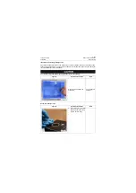
Refer to Pressure Release of Hydraulic system to release the pressure of service brake system
and parking brake system before removing the brake cylinder.
Figures
Operation instruction
Tools
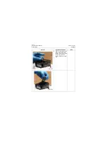
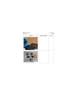
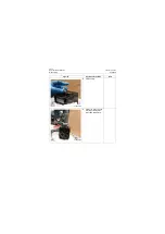
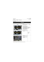
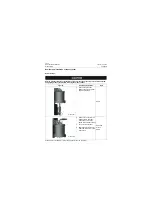
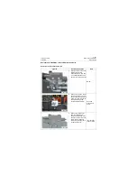
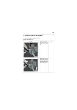
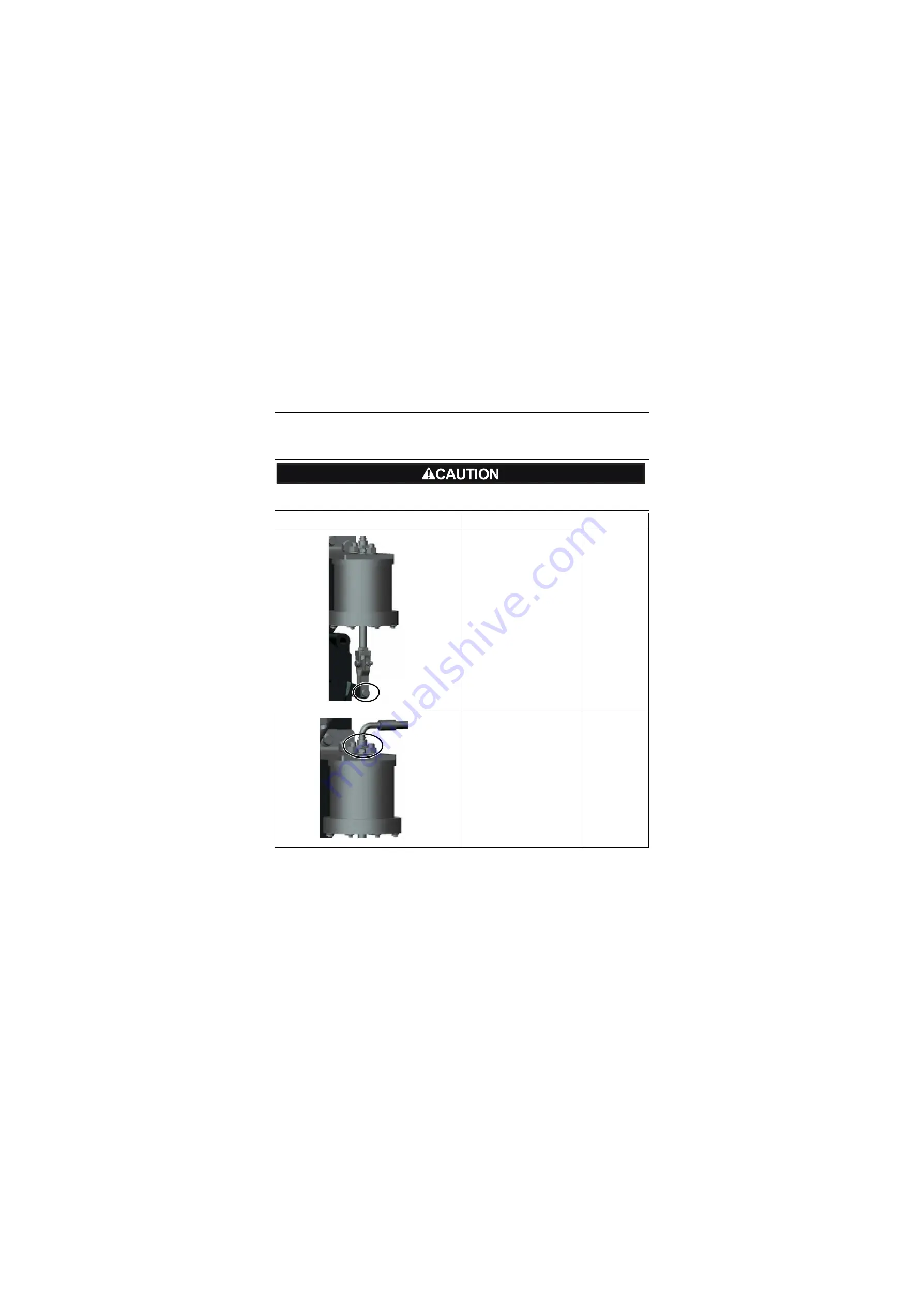
1. Remove the pin shaft
between the brake cylinder
and manual brake;
Pliers
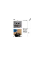
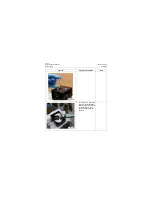
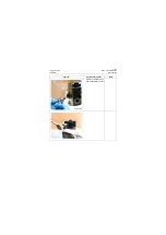
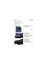
2. Remove the hose from the
brake cylinder, and then
loosen the nuts from the
above end of brake cylinder;
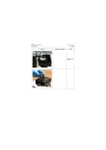
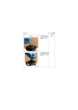
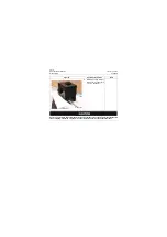
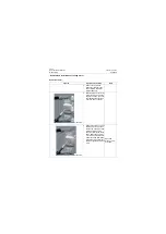
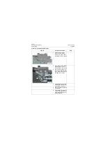
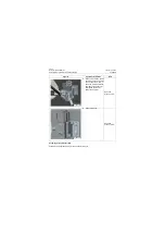
3. Take out brake cylinder;
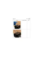
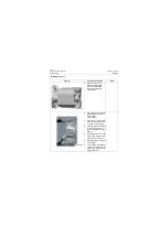
4. Shield the port of brake cyl-
inder and store it in dry and
clean place.
Open-end
wrench:
24mm
P18H00351
P18H00352
Summary of Contents for CLG835H
Page 2: ......
Page 4: ...Contents January 24 2017 CLG835H...
Page 6: ...1 2 General Information January 24 2017 CLG835H...
Page 38: ...1 34 Machine Inspection Table January 24 2017 CLG835H...
Page 156: ...3 2 Power Train System January 24 2017 CLG835H...
Page 214: ...3 2 Power Train System January 24 2017 CLG835H...
Page 272: ...3 60 Testing and adjustment January 24 2017 Power Train Test CLG835H...
Page 276: ...4 4 Hydraulic System January 24 2017 CLG835H...
Page 552: ...6 2 Driver s Cab System January 24 2017 CLG835H...
Page 608: ...7 2 Structure January 24 2017 CLG835H...
Page 662: ...8 4 Electrical System January 24 2017 CLG835H...
Page 677: ...8 19 January 24 2017 Structure Function Principle CLG835H Power System P18E00014...


