4-227
January 24, 2017
Removal and Installation
CLG835H
Brake system
Removal and installation of solenoid directional valve
Removal of solenoid directional valve
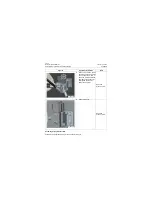
Figures
Operation instruction
Tools
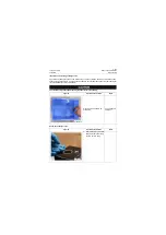
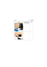
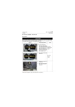
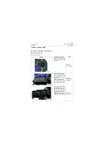
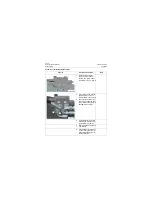
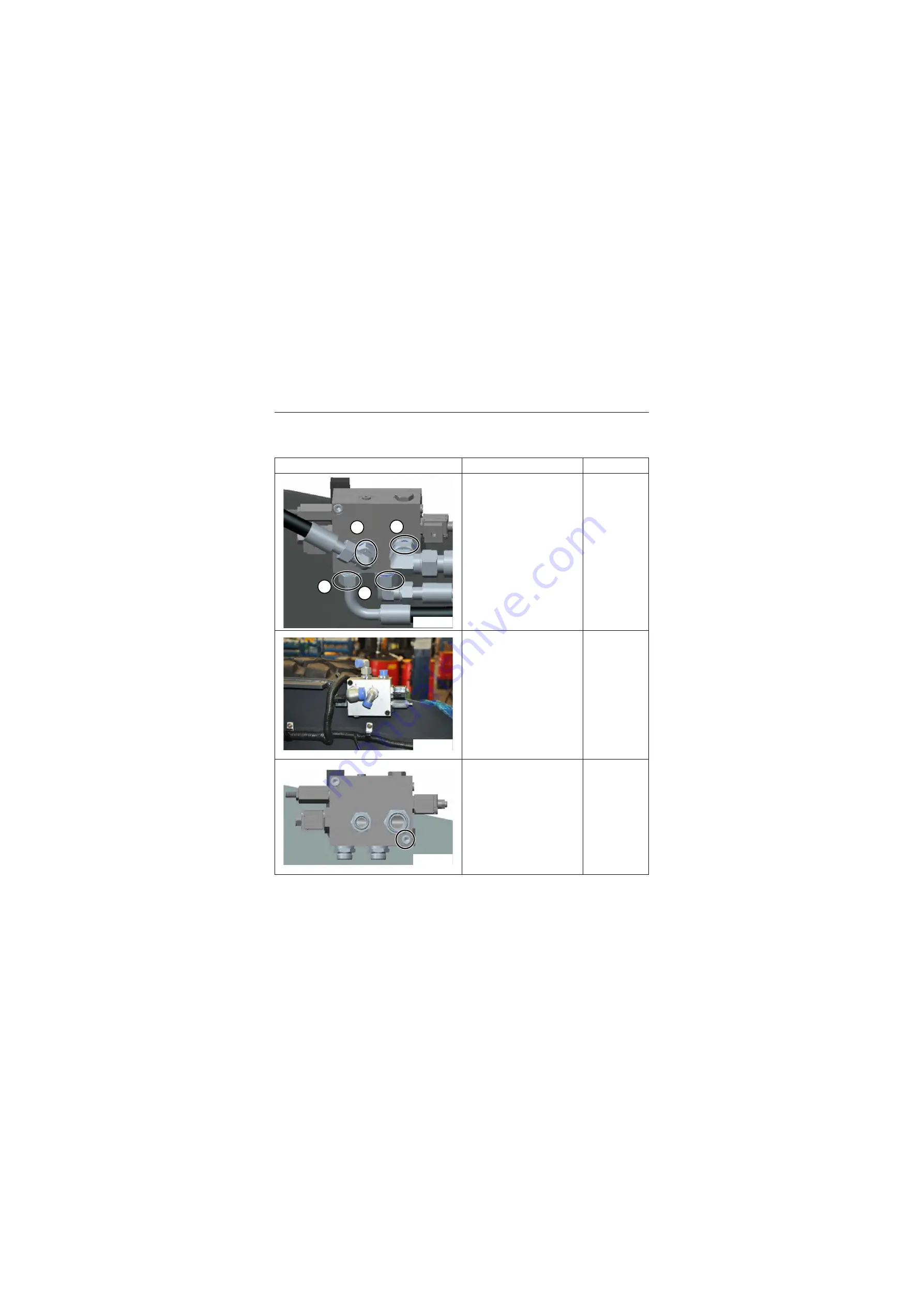
1. Mark the hoses on the sole-
noid directional valve
respectively as: A, B, P and
T. The identification should
be clear, firm and not fall off.
Marker
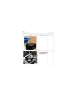
2. Remove A port hose, B port
hose, P port hose and T port
hose; Loosen the hose joints
with wrench and remove the
hose joints after gentle
knockdown. Mask joints;
Open-end
wrench: 32m,
41mm
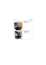
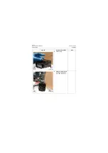
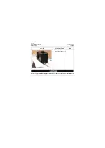
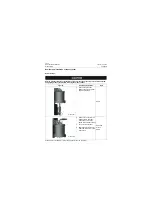
3. Remove the captive bolt
from the solenoid direc-
tional valve mounting plate,
and place it in the clean con-
tainer; avoid collisions to
ensure the personnel secu-
rity during removal;
Inner hexagon
spanner: 8mm
P18H00365
B
P
T
A
P18H00366
P18H00367
Summary of Contents for CLG835H
Page 2: ......
Page 4: ...Contents January 24 2017 CLG835H...
Page 6: ...1 2 General Information January 24 2017 CLG835H...
Page 38: ...1 34 Machine Inspection Table January 24 2017 CLG835H...
Page 156: ...3 2 Power Train System January 24 2017 CLG835H...
Page 214: ...3 2 Power Train System January 24 2017 CLG835H...
Page 272: ...3 60 Testing and adjustment January 24 2017 Power Train Test CLG835H...
Page 276: ...4 4 Hydraulic System January 24 2017 CLG835H...
Page 552: ...6 2 Driver s Cab System January 24 2017 CLG835H...
Page 608: ...7 2 Structure January 24 2017 CLG835H...
Page 662: ...8 4 Electrical System January 24 2017 CLG835H...
Page 677: ...8 19 January 24 2017 Structure Function Principle CLG835H Power System P18E00014...

