


7-41
January 24, 2017
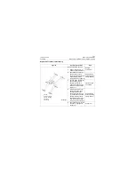
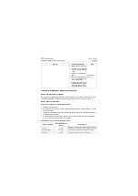
Removal and Installation
CLG835H
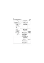
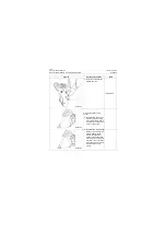
Removal and installation of work implement system
Removal and installation of quick coupler bucket and quick coupler frame
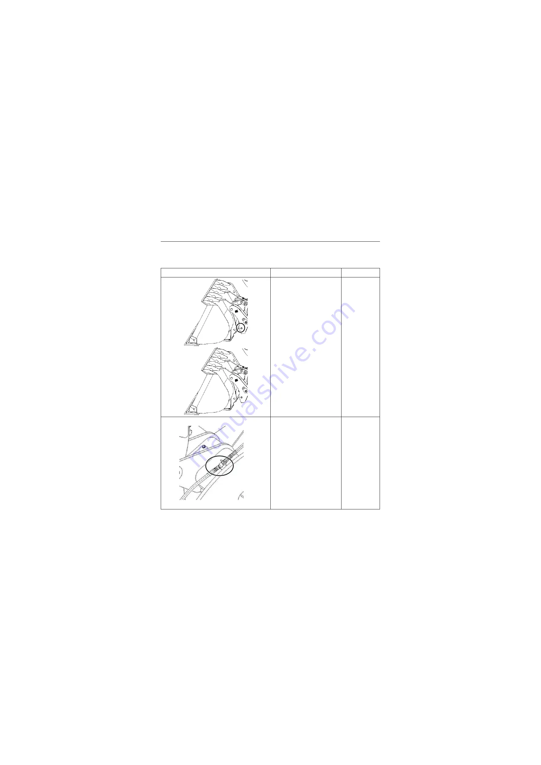
Removal of quick coupler bucket and quick coupler frame
Figures
Operation instruction
Tools
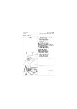
1. Remove the quick coupler
bucket
1) Start the machine, put the
boom in the lowest position,
lay flat the bucket
2) Operate the third linkage of
pilot lever, and then retract
the quick coupler bucket pin
to the quick coupler frame.
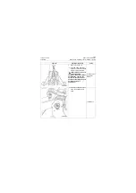
3) Separate the quick coupler
frame from the bucket.
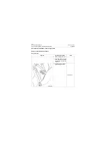
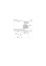
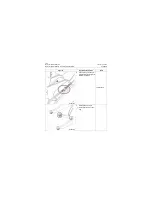
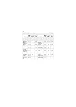
2. Remove the quick coupler
multi-functional pipe joint
1) Operate the complete
machine, lower the boom to
the lowest position and lean
forward the quick coupler
frame for a proper angle,
then shut it off.
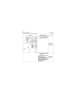
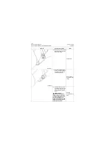
2) Remove the quick coupler
multi-functional pipe joint at
left and right sides, and
then collect the hydraulic oil
drained from the pipe with a
drip pan to prevent contami-
nating the ground.
30# Wrench
P18S00064
P18S00065
P18S00066
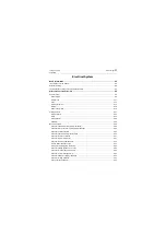
Summary of Contents for CLG835H
Page 2: ......
Page 4: ...Contents January 24 2017 CLG835H...
Page 6: ...1 2 General Information January 24 2017 CLG835H...
Page 38: ...1 34 Machine Inspection Table January 24 2017 CLG835H...
Page 156: ...3 2 Power Train System January 24 2017 CLG835H...
Page 214: ...3 2 Power Train System January 24 2017 CLG835H...
Page 272: ...3 60 Testing and adjustment January 24 2017 Power Train Test CLG835H...
Page 276: ...4 4 Hydraulic System January 24 2017 CLG835H...
Page 552: ...6 2 Driver s Cab System January 24 2017 CLG835H...
Page 608: ...7 2 Structure January 24 2017 CLG835H...
Page 662: ...8 4 Electrical System January 24 2017 CLG835H...
Page 677: ...8 19 January 24 2017 Structure Function Principle CLG835H Power System P18E00014...


