LSLB 10 B2
■
32
│
GB
│
IE
♦
Replace the cover of the connection box and screw it firmly into
place.
♦
You can now switch the power supply back on.
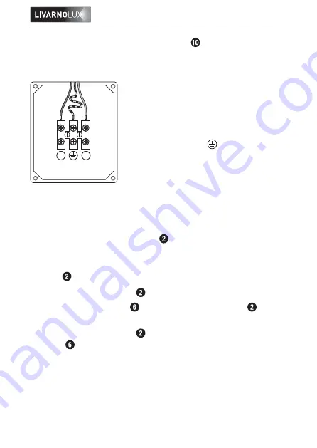
N
L
Brown or black wire (L)
Blue wire (N)
Green/yellow wire ( )
Fig. connection diagram
Alignment of the motion detector
When aligning the motion detector , make sure that the detection
range does not include any undesired areas, such as streets or lights.
Ensure that no objects block the line of sight between the motion
detector and any possible trigger.
♦
Align the motion detector horizontally by turning it.
♦
Undo the locking screw to adjust the motion detector verti-
cally.
♦
Align the motion detector and then re-tighten the locking
screw .
Summary of Contents for LSLB 10 B2
Page 3: ......

