background image


LiveU Live Video 

Uplink System 

User Guide 

(LU60 and LU70) 

Version 6.3 

Part Number:   DOC00032 


Summary of Contents for LU60

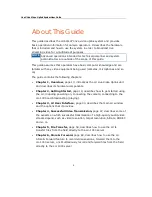
Page 1: ...LiveU Live Video Uplink System User Guide LU60 and LU70 Version 6 3 Part Number DOC00032...

Page 2: ...link unit and describes its hardware components Chapter 2 Getting Started page 19 describes how to get started using the LU including powering on connecting the camera connecting to the LU 1000 and br...

Page 3: ...ack When using the device outside the LU backpack follow the safety instructions in Appendix D in order to avoid shorting the battery Appendix D Safety and Maintenance page 139 describes how to mainta...

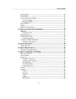
Page 4: ...ep 1 Turning On the LU Device 20 LU60 LU70 Turning On the Device 20 Main User Window 22 Step 2 Connecting the Video Camera 23 LU60 LU70 Connecting the Camera 24 Step 3 Connecting to the LU 1000 26 Con...

Page 5: ...ile 50 Profile Descriptions 51 Changing a Profile s Resolution 55 Resolution Descriptions 56 Chapter 5 File Transfer 59 Transferring Files 59 Chapter 6 Store Forward 63 Storing and Forwarding Files 63...

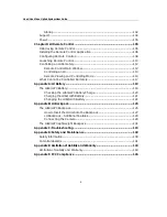
Page 6: ...17 Appendix A LU Battery 119 The LU60 LU70 Battery 119 Checking the LU60 LU70 Battery Charge 120 Charging the LU60 LU70 Battery 121 Changing the LU60 LU70 Battery 122 Appendix B LU Backpack 125 The LU...

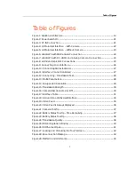
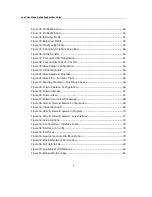
Page 7: ...tion Failed 27 Figure 12 Connecting Transmission Test 28 Figure 13 Profile Parameters 28 Figure 14 Unsupported Resolution 29 Figure 15 Transmission Strength 30 Figure 16 Camera Disconnected or Off 30...

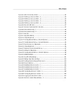
Page 8: ...Video Input 66 Figure 43 Warning Message Not Enough Space 66 Figure 44 Forward Session Configuration 66 Figure 45 Forward Browse 67 Figure 46 Forward Icon 67 Figure 47 Forward completed message 68 Fig...

Page 9: ...n Window General Options 95 Figure 75 Touch Screen Configuration 96 Figure 76 Virtual Keyboard 96 Figure 77 Network Connections Window 97 Figure 78 WiMax Configuration 98 Figure 79 Configuration Windo...

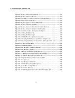
Page 10: ...Uplink Unit Top View 121 Figure 104 Opening the Battery Compartment Lifting the Tab 122 Figure 105 Opening the Battery Compartment Pulling Open the Cover 122 Figure 106 Pulling Out the Battery 123 Fig...

Page 11: ...laza Drive Suite 505 Hackensack New Jersey 07601 USA Tel 1 201 742 5228 Fax 1 201 623 4838 USA and the Americas info_us liveu tv International info liveu tv Technical Support For 24 7 support call US...

Page 12: ...LiveU Live Video Uplink System User Guide 12 Blank page for double sided printing...

Page 13: ...ia the Ethernet LAN It is designed to transmit high quality live streaming video from the field for any type of event such as breaking news sports or live interviews without the need for costly satell...

Page 14: ...broadcasting center The LU 1000 server gathers the live video feed via a secure Internet connection and is then able to supply this feed to the production suite routing table website and such for fur...

Page 15: ...U system s flexibility enables users to select different configurations for certain situations where it may be necessary to manually reconfigure the original setup For example when the required bandwi...

Page 16: ...U Device Types LiveU provides the LU60 LU70 family of products for professional broadcast applications These products have a proprietary internal antenna array that extends cellular range extends cell...

Page 17: ...posite and S Video DV FireWire 1394 Video IN The relevant cables are provided for each HDMI cable BIDs are required in order to ensure compatibility with FCC standards If your kit does not include the...

Page 18: ...LiveU Live Video Uplink System User Guide 18 Blank page for double sided printing...

Page 19: ...e workflow described in this chapter NOTE You may connect non DV cameras to the LU before turning on the LU Step 1 Page 20 Step 2 Page 23 Step 3 Page 26 Step 4 Page 30 Step 5 Page 30 If required you m...

Page 20: ...tion on how to charge the battery IMPORTANT For DV cameras it is recommended to first power on the LU60 LU70 as described below and then to connect the camera SDI HDMI or Analog cameras can be connect...

Page 21: ...up Figure 2 Power Switch On TIP It is good practice to keep the unit plugged into a power outlet when it is not in use in order to keep it charged and ready for operation Make sure that the DC IN powe...

Page 22: ...een becomes active and the user interface appears as shown below If the camera has been connected powered on and then automatically detected by the LU a preview of the video feed is automatically disp...

Page 23: ...erface on page 33 Step 2 Connecting the Video Camera The procedure for connecting a video camera to a LU live video uplink unit is simple Only one camera can be connected directly to the LU unit at an...

Page 24: ...e 1394 Figure 6 LU60 LU70 with SDI Camera Connection For an SDI camera only use the middle SDI connector HDMI Analog Component Composite and S Video DV FireWire 1394 Figure 7 LU60 LU70 with DV HDMI an...

Page 25: ...relevant port on the video camera IMPORTANT NOTE FOR DV FIREWIRE CAMERAS In order to avoid permanent damage to a FireWire DV camera and the LU Live video uplink unit you must only use the LiveU provi...

Page 26: ...video using the LU Live Video Uplink system it is necessary to connect the unit via the Internet to the LU 1000 server using one or more wireless networks The LU 1000 server is usually located at the...

Page 27: ...nes the best parameters for ensuring that the system functions at maximum efficiency After this calibration the LU application is able to calculate the overall system efficiency total effective bitrat...

Page 28: ...Test The process finishes when all the available interfaces have been connected and the LU unit has finished analyzing the connection and calibrating the system This is an internal process that runs...

Page 29: ...has an red The end to end delay for the selected Profile is also displayed as shown above When the Interview Profile is selected the Recommended Optimal delay is displayed as shown above An icon appea...

Page 30: ...gth Step 5 The Next Step After you have finished playing you can tap the Stop button If you turn off the camera during playing then an Error status appears If you tap the Error status indicator then a...

Page 31: ...terfaces after a long time has passed since calibration was performed meaning since the Connect button was pressed or immediately after transmission conditions have changed for example from stationary...

Page 32: ...he Options button Configuration button Media button For more information refer to Chapter 7 Configuration and Settings on page 73 NOTE The LU60 LU70 products that support dual SIM are provided with mo...

Page 33: ...page 34 Video Feed page 35 Camera Connectivity Icon page 36 Battery Indicator Icon page 37 Transmission Quality page 38 IFB Indicator page 39 Status Indicator page 41 Rotate Screen page 42 Unlock Loc...

Page 34: ...rolling the unit and its broadcast Figure 18 LU Live Video Uplink User Interface The following describes the various elements in the main window NOTE It is possible to add a USB enabled keyboard and m...

Page 35: ...splayed a few seconds after the camera is connected and automatically detected by the LU Figure 19 Video Feed NOTE The video is only transmitting after you tap the Play button and the On Air status in...

Page 36: ...Figure 20 Video Feed is Always Displayed Camera Connectivity Icon The Camera connectivity indicator shows the current status of the camera connection as follows Table 1 Camera Connectivity Indicator I...

Page 37: ...lows Table 2 Battery Indicator Icon Status Icon Description LU is running off internal battery The indicator shows that the battery is fully charged partially charged or empty The unit is connected to...

Page 38: ...e LU60 LU70 Battery Charge section on page 120 for a description of the battery charge indicator in the battery compartment Transmission Quality Figure 24 Transmission Quality This indicator shows the...

Page 39: ...button is tapped and the LU is connected to the LU 1000 the LU connects to the IFB server and retrieves a list of all the available IFB channels These channels are then displayed for your selection I...

Page 40: ...he IFB button displays the following window Figure 25 IFB Configuration Window To configure the IFB channel 1 Select one of the IFB channels provided by the IFB server from the displayed list 2 Click...

Page 41: ...color of the indicator and the text indicate the unit s status as follows Table 4 Status Icons Status Icon Description Off red light Appears before the Connect button is tapped which means that the sy...

Page 42: ...ot responding Error Video input not detected Warning yellow light Warning X packet s lost Warning X missing interface s Transferring green light FTP mode is active Files are being transferred Rotate S...

Page 43: ...document Connect Reconnect Button Connect Button The LU detects all available interfaces immediately when the unit boots These interfaces can be seen in the Interface window but the BW and Delay of ea...

Page 44: ...If you tap the Interface button and see a low BW kbps and or high Delay sec for each or some of the interface rows If you tap the Profiles button and see an red on the desired Profile button or on th...

Page 45: ...ormation about the selected Profile and to select a different Profile or reconfigure the settings of a Profile A full description about the Profiles provided for the LU and how to select them is provi...

Page 46: ...LiveU Live Video Uplink System User Guide 46 Blank page for double sided printing...

Page 47: ...igh quality audio video stream depends on a number of elements such as video resolution target resolution bitrate CODEC and so on The LU unit analyzes the current network conditions and sets the optim...

Page 48: ...st is an interview after the game then a lower bitrate is effective If the broadcast is for the Internet it is not always necessary to use a resolution greater than CIF or half D1 Profiles Window This...

Page 49: ...that the interface quality is insufficient to support the selected Profile and Resolution then the device does not transmit You can then select a different Profile and or Resolution Figure 30 Profile...

Page 50: ...device which are the same for both SD and HD cameras The currently selected Profile appears highlighted Its name is indicated at the top of the Profile button The bottom of the window displays the se...

Page 51: ...Profile page 51 Balanced Profile page 52 Max Quality Profile page 54 Interview Profile Select the Interview Profile when you need a short end to end delay This Profile provides the maximum quality wit...

Page 52: ...ion and depends on the selected resolution The Recommended delay checkbox is automatically selected to indicate that this Profile is using the automatically delay set by the system after calibration Y...

Page 53: ...rmally uses fewer modems by eliminating those with relatively high delay in order to reduce transmission latency As it optimizes the system for a relatively short delay 5 12 seconds it is subject to i...

Page 54: ...ons in order to gain the maximum bandwidth possible and configures the system to deliver the best resolution Max Quality Profile Delay Max Quality profile allows for the longest delay 12 60 seconds to...

Page 55: ...deo frame picture that is transmitted and whether it is for NTSC or PAL analog television encoding systems The bottom area of each Profile button displays the currently selected resolution The same re...

Page 56: ...nnot select whether to enable disable modems on the fly Profiles Resolutions or Custom delay cannot be changed during broadcast In order to change the bitrate it is necessary to stop the transmission...

Page 57: ...smission rate under harsh conditions However it is possible to start working with HD from 400 Kbps and upwards if necessary This resolution is available in either NTSC or PAL frame rates HD 960x540 Th...

Page 58: ...in this case is approximately 512 Kbps The optimal bitrate for Half D1 is between 750 Kbps and 1 5 Mbps VGA NTSC Only PAL 640x480 This provides near Full D1 quality which is used by some websites Use...

Page 59: ...can be transferred from the LU unit itself or from a USB device such as a camera with USB interface attached which can be attached to the LU unit One or more files can be selected to be transferred T...

Page 60: ...ted on the LU or on the disk on key inserted into the LU The right side of the window displays the list of files that have been selected to be transferred 4 Use the browse button to go up one director...

Page 61: ...t transferring the files in the list on the right to the LU 1000 server NOTE To remove a selected file from the list on the right simply select it and then tap the left arrow button After the transmis...

Page 62: ...LiveU Live Video Uplink System User Guide 62 Blank page for double sided printing...

Page 63: ...ansfer prerecorded files or simultaneously store and forward the recorded file to the LU 1000 server The Store Forward feature enables you to transfer files under the optimal conditions in terms of qu...

Page 64: ...o display the following window and tap the Store button to display Store related fields Figure 39 Store Session Configuration 3 Fill in the fields as follows Session Name The name assigned to the reco...

Page 65: ...tion Sets the resolution options according to the connected camera Standard or HD The set resolution determines the video rate To set the resolution tap the arrow and select from the drop down list Vi...

Page 66: ...connecting the camera recording is automatically resumed Figure 42 Store Error No Video Input If the LU is about to run out of memory space a warning appears in red and the store process is stopped un...

Page 67: ...e end of the forwarding session 5 If the forwarded file is located on the device it is automatically deleted when forwarding is completed Therefore when forwarding a session locally the Delete session...

Page 68: ...Figure 47 Forward completed message To store and forward recorded files 1 If the file to be stored and forwarded is on a USB Disk on Key then insert it into the LU unit 2 Tap the Upload button and the...

Page 69: ...SB Disk on Key Tap the arrow to select the relevant option from the drop down list Time Left The memory space left for the recording is calculated according to the set resolution and video rate and is...

Page 70: ...forwarding a session locally the Delete session on arrival to server option is checked automatically and cannot be unchecked When forwarding a session from a USB Disk on Key you can decide whether to...

Page 71: ...ge appears The session is resumed when the connection to the server is restored Figure 51 Store Forward Session server is busy 8 To stop the Store part of the session tap Stop Store To stop the Forwar...

Page 72: ...LiveU Live Video Uplink System User Guide 72 Blank page for double sided printing...

Page 73: ...u to monitor the configuration and performance of the Interfaces as well as adjust the setup of the device as needed It also enables you to display the number for getting support reset the system to s...

Page 74: ...configuration settings and servers It also enables you to access remote support and to restart or power down the unit Figure 52 Setup Options The Options button provides the following configuration o...

Page 75: ...rmation is displayed for each interface A more detailed description is provided for some of these fields on page 78 Interface Status Icon Represents a cellular network Represents cellular interfaces o...

Page 76: ...do not display a letter A or B in this window Interfaces dropdown list This dropdown list enables you to specify the interfaces to be used for transmission The following options are available Use All...

Page 77: ...You may refer to the Defining a Wi Fi Interface section on page 79 for a description of how to define a Wi Fi interface You may refer to the Xtender Wi Fi Link section on page 86 for a description ab...

Page 78: ...box indicating whether an interface should use a guaranteed bandwidth rate for transmission in order to ensure reliable transmission When selecting this checkbox you should specify the maximum uplink...

Page 79: ...matically stores and reuses the latest passwords that you entered for each Wi Fi network A single bar appears in the Interfaces page as described in the Interfaces section on page 75 to represent all...

Page 80: ...ss Network Connection row as shown below Figure 58 Wi Fi Interfaces The following window is displayed listing the currently available Wi Fi networks near the LU and all the Wi Fi profiles that were sa...

Page 81: ...on any Wi Fi network row that has an icon to display the following window in which you can enter the Network Key password that enables access to this Wi Fi network Figure 60 Wireless Network Key Once...

Page 82: ...ap this button to deactivate this Wi Fi network so that it is not used during transmission Access Point Button Tap this button to define the LU as an Access Point This LU can then provide an Internet...

Page 83: ...etwork when it is detected even if it is not higher in the list than other detected networks Access Point The LU can serve as an access point This means that it can enable a wireless device s such as...

Page 84: ...User Guide 84 3 Tap the Wireless Network Connections row The following window is displayed Figure 63 Defining an Access Point 2 4 Tap the Access Point button The following window is displayed Figure...

Page 85: ...Access Point 8 You can check the Auto start after connect field to specify that the LU automatically operates as an Access Point using this Wi Fi network after it powers on NOTE The Auto start after c...

Page 86: ...e main window as shown below Figure 65 Defining an Access Point 4 Xtender Wi Fi Link Wi Fi link statistics can be viewed in the Interfaces window NOTE The Xtender Wi Fi link LAN should only be connect...

Page 87: ...inent to which the unit was delivered Channel The 802 11n frequency channel currently in use Bandwidth The used bandwidth which is the maximum possible according to the specified Country Code SSID The...

Page 88: ...ually select another network other than the one to which the modem is registered This feature is not relevant for Wi Fi or LAN interfaces To manually select another network 1 In the main window tap th...

Page 89: ...uration and Settings 89 4 Tap an interface row to display the following window Figure 69 Manual Roaming 2 5 In the Operator dropdown list select the operator network with which to work 6 Tap the Save...

Page 90: ...s button enables you to view select and define LU 1000 server connections Tapping this button displays a list of the previously defined Servers as shown below Figure 70 Servers To select the Server us...

Page 91: ...gure 71 Server Definitions 2 Fill in the following fields to define a Server Name The name of the LU 1000 server to receive the broadcast Tap in this field to display a keyboard as shown below Figure...

Page 92: ...erver If the server is connected to the Internet through a firewall or NAT router then the port must be open for access from the public Internet on the LU 1000 s side 3 Tap OK Settings The Settings bu...

Page 93: ...ove in Figure 73 The H 264 CODEC is an improved video encoder It allows near realtime encoding and supports an adaptive bitrate which increases resiliency If the bitrate drops then the video stream do...

Page 94: ...hes this process Automatic FPS Reduction Specifies that the LU monitors network conditions and dynamically reduces the transmitted video s frames per seconds if needed in order to provide more stable...

Page 95: ...gs 95 General The General tab shown below enables you to define general unit settings such as for the screen keyboard and network and to use an explorer browsing tool as follows Figure 74 Configuratio...

Page 96: ...Screen Tap the Screen button to configure the touch screen The following window is displayed Figure 75 Touch Screen Configuration Keyboard Tap the Keyboard button to display a virtual keyboard which e...

Page 97: ...ich enables you to browse the network drives For example as shown below Figure 77 Network Connections Window Explore Tap the Explore button to display a standard Windows explorer window NOTE The Advan...

Page 98: ...search for and connect to WiMax networks in the area of the LU device The following window is displayed Figure 78 WiMax Configuration xTender The xTender tab shown below enables you to configure the...

Page 99: ...ould be made according to the interface that is used to connect between the LU60 LU70 and the Xtender as follows When using a USB interface select USB When using an Ethernet interface select LAN When...

Page 100: ...w B option and then click Run The device burns a new Access Point Name APN specifying the details of the cellular network operator on each module and then restarts the system using the selected SIM ca...

Page 101: ...to specify what is played and transmitted when you press the Play button in the main window Figure 81 Input Media Settings Typically the Camera option shown above is selected which specifies that the...

Page 102: ...opping or Select the Infinite option to play the video in an endless loop until you stop it Startup The Startup tab shown below enables you to define the LU s behavior immediately after it is powered...

Page 103: ...u to get external support from the LiveU support team if there are problems with the LU live video uplink unit while working in the field LiveU technicians use third party software to access the unit...

Page 104: ...y the following options Figure 84 Power Options This button is no longer applicable To power off the device press the ON OFF button shown in Figure 2 on page 21 Exits the application shuts down the LU...

Page 105: ...0 Controlling an LU Remotely page 112 What Cannot be Controlled Remotely page 117 Introducing Remote Control Remote Control is a standalone application that enables you to control an LU device remotel...

Page 106: ...ity that an LU operator can perform on the device can be performed remotely using the Remote Control application excluding the options described in the What Cannot be Controlled Remotely section on pa...

Page 107: ...wing window is displayed Figure 86 Installing Remote Control 2 3 Click the Next button and wait until the following successful message window is displayed Figure 87 Installing Remote Control 3 4 Click...

Page 108: ...plication browse to the following folder C Program Files LiveU appData RemoteControlHD config 2 Open the ServersData file using a standard text editor For example as shown below Figure 88 Configuring...

Page 109: ...Open the server ini file using a standard text editor In the section called Control the remote_control_port parameter specifies the port through which that LU Server communicates with the Remote Contr...

Page 110: ...unch the Remote Control application 1 From the Start menu select All Programs LiveU Remote Control Remote Control The following window is displayed Figure 90 Logging into Remote Control 2 In the User...

Page 111: ...LU Remote Control 111 3 Click the Login button The following window is displayed Figure 91 Remote Control Main Window 1...

Page 112: ...lication as described above the main window is displayed as shown below Figure 92 Remote Control Main Window 2 The pane on the left lists the LUs that are connected to the LU 1000 s to which the Remot...

Page 113: ...cative names for each LU you may refer to the Identifying the LU Unit section of the LU 1000 Studio Server User Guide The Refresh button must be clicked in order to display the latest list and status...

Page 114: ...U Device Screen Remote Viewing and Controlling Mode Viewing Mode By default when the user interface of the selected LU device is first displayed as described above you are only able to view the settin...

Page 115: ...n by saving If you try to change settings and then save the error message Remote Control is disabled is displayed as shown below Figure 97 Remote Control is Disabled Controlling the LU To start contro...

Page 116: ...Remote Control Enabled NOTE While the LU is being controlled the LU operator can still use the user interface options but cannot stop the Remote Control application from controlling the device remotel...

Page 117: ...ality that an LU device operator can perform can be controlled remotely using the Remote Control application excluding the following Servers The option to switch the LU 1000 server to which the LU dev...

Page 118: ...utton Forward The Store Forward feature enables you to store recorded files to transfer prerecorded files or to simultaneously store and forward the recorded file to the LU 1000 server The option to F...

Page 119: ...LU70 Battery page 121 Changing the LU60 LU70 Battery page 122 The LU60 LU70 Battery The LU60 LU70 live video uplink system consists of a computerized unit that works on either a battery or standard A...

Page 120: ...tip can be displayed while the battery is being used and is not being charged It shows how much longer the battery will last Figure 101 Battery Status Tool Tip You may refer to Battery Indicator Icon...

Page 121: ...nit s external power supply may be operated on any electric system 110V or 220V without the need for a transformer However it may be necessary to use an adaptor plug depending on the type of electrica...

Page 122: ...s battery even while it is transmitting without disturbing the flow To change the battery 1 To open the battery compartment cover lift the thin black tab as shown below Figure 104 Opening the Battery...

Page 123: ...tery is shown below Figure 107 LU60 LU70 Battery 4 Insert another battery making sure to align the electrical contacts on the battery with the socket inside the LU60 LU70 5 After the battery is in pla...

Page 124: ...LiveU Live Video Uplink System User Guide 124 Blank page for double sided printing...

Page 125: ...pack LU60 LU70 should be only installed in the backpack as specified in the section below The use of any other backpack is prohibited and may cause permanent damage to the device The LU60 LU70 Backpac...

Page 126: ...rm inside the backpack that enables airflow Figure 108 LU Backpack Closed for Storage This specially designed backpack enables the camera operator to be totally mobile while operating the LU since it...

Page 127: ...e direction shown below making sure to keep the top of the unit where the touch screen is situated facing the front of the bag The base of the LU goes in first so that its ventilation holes are sittin...

Page 128: ...r the small window on the front of the bag The flap can be secured so that it protects the LCD from sunlight making it easier to read the user interface when working outdoors in bright sunlight Secure...

Page 129: ...U unit In addition there are zippered compartments for personal accessories and an attached rain hood that can be used to protect the entire backpack Figure 113 Zippered Openings for Connecting Wires...

Page 130: ...LiveU Live Video Uplink System User Guide 130 Figure 115 LU Backpack Rain Hood The top opening has an attached rain hood that protects the entire backpack in mildly inclement conditions...

Page 131: ...ll as ease of use for the camera operator Similar in functionality to the LU60 LU70 backpack the lightweight backpack has the following additional features Smaller in size and more comfortable to carr...

Page 132: ...LiveU Live Video Uplink System User Guide 132 Blank page for double sided printing...

Page 133: ...urce using the supplied charger If the LED on the enclosure still does not light up then either the charger or the unit itself may be damaged Contact your LiveU representative Camera not working nothi...

Page 134: ...ture quality Move the unit for instance closer to a window or outside to improve wireless reception Broadcasting from international locations Contact the LiveU support team to adjust the unit by insta...

Page 135: ...e air inlets and outlets Make sure that the air flow path is not obstructed The error message System temperature critical appears on the LU unit To prevent permanent damage the system will shut down a...

Page 136: ...264 player should appear Drag the H 264 player window to the desired position Adjust the size of the H 264 window using the standard window resizing controls bottom right of the window From the H 264...

Page 137: ...of the buttons This icon is a warning that minimal interfaces are used which may result in degraded video quality It is not mandatory but if you want to improve the video quality you can select a dif...

Page 138: ...LiveU Live Video Uplink System User Guide 138 Blank page for double sided printing...

Page 139: ...rocedures other than those specified in the manual may result in exposure to shock and or electrical or mechanical hazards CAUTION Avoid shorting the battery Do not immerse it in water Do not disassem...

Page 140: ...oduct off and contact the support Refer to the following figure for power input pinout Figure 118 Power Input Pinout Avoid leaving the product unprotected in direct sunlight for more than five minutes...

Page 141: ...should be operated according to the same rules and limitations as expected from normal cellular devices Do not operate the LU Client Enclosure in an environment that may be susceptible to radio interf...

Page 142: ...rea where medical equipment life support equipment or near any equipment that may be susceptible to any form of radio interference In such areas the host communications device must be turned off The L...

Page 143: ...d to implied warranties of merchantability and fitness for a particular purpose and non infringement Under no circumstances shall the company be liable for any damages whatsoever including without lim...

Page 144: ...NSE IS GRANTED OR SHALL BE IMPLIED FOR ANY OTHER USE ADDITIONAL INFORMATION MAY BE OBTAINED FROM MPEG LA L L C SEE HTTP WWW MPEGLA COM Notice Required for the License Granted under Article 2 6 and for...

Page 145: ...nce to radio or television reception which can be determined by turning the equipment off and on the user is encouraged to try to correct the interference by one or more of the following measures Reor...

Page 146: ...US and International 2 University Plaza Drive Suite 505 Hackensack New Jersey 07601 USA Tel 1 201 742 5228 Fax 1 201 623 4838 USA and the Americas info_us liveu tv International info liveu tv...

Reviews: