background image

26

User’s manual

EN

INITIAL START-UP

Check that the grassy surface of the lawn to mow has a height which is compatible with the 

1. 

proper functioning of the robot (see technical specifi cations on page 9).

Adjust the desired cutting height (see cutting height adjustment on page 22).

2. 

Check that the work area is correctly delimited and that there are no impediments to the 

3. 

correct functioning of the robot as indicated in the section “Preparation and defi ning  the 
boundaries of the work areas” and following sections.

Disconnect the robot from the recharging area (page 21).

4. 

Position the robot inside the grassy surface in an area where the grass is at least 1 metre (40.0 

5. 

in.) from any obstacle.

Press the OFF/ON key and wait a few seconds for the robot to turn on completely.

6. 

Press START/STOP key to start the robot.

7. 

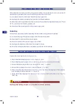
Once the robot has stopped due to the reasons described in the chapter “Robot Stop”, activate 
the safety stop and reposition the robot inside the power supply unit for recharging (see page 21).

ROBOT SAFETY STOP

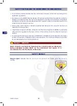
When using the robot, it may become necessary to stop it safely to prevent the blade from 
accidentally starting. Press the “ON/OFF” key.

The robot safety stop is necessary when carrying out any maintenance and 
repairs (for example: cleaning, adjustments to cutting height, etc.).  

For a better cutting performance and correct functioning of the recognition 
sensor, do not start the robot in case of rain or in very humid conditions. The best 
results are obtained in the middle of the day.

Important

Important

Summary of Contents for M Line L50EU

Page 1: ......

Page 2: ...EN ISO 9001 empresa de software que desde el año 1982 ha consolidado su propia actividad y presencia en el mercado internacional Aplicar soluciones informáticas avanzadas al sector de la automatización industrial significa optimizar las actividades productivas y simplificar los procedimientos de trabajo Este producto es fruto de la constante actividad de investigación de los laboratorios ZUCCHETTI...

Page 3: ... 37 CE 73 23 CEE 89 336 CEE Para estas últimas están incluidas las enmiendas sucesivas Verklaring van overeenstemming 98 37 EG bijlage II punt A ZUCCHETTI Via Lungarno 305 A Terranuova B ni AR ITALIA verklaart dat de machine waarvan de identificatiegegevens hiernaast worden vermeld en die bedoeld is om gras te maaien in huishoudelijke en andere omgevingen voldoet aan de richtlijnen 98 37 EG 73 23 ...

Page 4: ...tting height adjustment 22 D Defining the boundaries of the work areas 15 Description of robot commands 23 G General description of the appliance 7 I Identification of manufacturer and appliance 6 Initial start up 26 L LED combinations meaning 24 M Main organs 8 Maintenance recommendations 29 Manual purpose of 5 Manufacturer and appliance identification 6 O Operating tips 29 Ordinary maintenance 2...

Page 5: ...8 Steep slopes 19 T Technical specifications 9 Tips operating 29 Troubleshooting 31 U Unpacking and packing 13 User recommendations 23 W Work areas preparation and boundaries 15 Reproduction even partial of this document without the Manufacturer s written authorisation is strictly forbidden The manufacturer implements a policy of continual improvement and reserves the right to modify this document...

Page 6: ... this manual in a safe and easily accessible place for quick reference Some information and illustrations contained in this manual may not perfectly correspond to the appliance in your possession however this does not compromise its functioning The manufacturer has the right to make changes without notice The following symbols are used throughout this manual to highlight some particularly importan...

Page 7: ... number and manufacturing year D Technical specifications REQUESTING TECHNICAL ASSISTANCE For any technical requirement please contact the Technical service centre of the Manufacturer or an authorised centre For technical assistance indicate the data reported on the data plate the approximate operating hours and the type of fault detected C Manufacturing year C Model B CE conformity label A Identi...

Page 8: ...ing again in the new direction Based on its operating principle random the robot automatically mows the entire delimited area of the lawn see figure The maximum lawn surface that the robot can mow depends on a series of factors such as the characteristics of the area irregular perimeters uneven surfaces divided areas etc the characteristics of the lawn type and height of the grass humidity etc the...

Page 9: ...trols the automatic functions of the robot D Control keyboard used to set and display the operating modes of the robot E Cutting blade mows the lawn F Electric motor operates the cutting blade E G Electric motor one operates the right wheel transmission unit while the other operates the left wheel H Sensors used to recognise the characteristics of the ground on which the robot is operating A B F G...

Page 10: ...nded maximum slope 27 depending on the grass conditions Ambient operating temperature 10 14 F Min 50 122 F Max Electric specifications Power supply unit for lithium battery Classe 2 Vin 90 264Vac AC current typ 1 2A 115Vac 0 7A 230Vac Input Frequency range 47 63Hz Type of Accumulators and Recharging Lithium ion rechargeable battery V A 25 2V 6 9Ah Battery Charger V A 29 3 Vcc 2 0 Ah Minimum time a...

Page 11: ...ow how to operate it and who have read and understood the instructions in this manual Only use the robot for the intended purposes specified by the manufacturer Improper use of the robot may lead to personal health and safety risks and economic losses Before using the lawn mower make sure that there are no objects on the lawn toys branches clothing items etc When using the robot make sure the work...

Page 12: ... when the mower strikes a solid object which will stop the movement in that direction and reverse itself away from the obstacle Inclinometer 3 If the robot works on a slope which is steeper than the maximum limit or tips over the robot will stop the movement in that direction and reverse to avoid the slope Emergency stop switch 4 Located on the top outer surface of the robot red in colour Pressing...

Page 13: ...c manner are marked with a special label Unauthorised disposal of Waste of Electric and Electronic Equipment WEEE is punishable with sanctions regulated by the laws in force in the territory where the infraction has been verified To implement the European directives 2002 95 CE 2002 96 CE 2003 108 CE in the Italian territory for example a legislative decree was issued No 151 of 25 July 2005 which p...

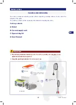
Page 14: ...r handling the robot Packing contents A Robot B Current supply unit C Spacer ring kit D User Manual INSTALLATION The list only includes standard parts Check the quantity and integrity of any optional accessories requested Keep the packing materials for subsequent use POWER SUPPLY UNIT ROBOT PACKING BOX RO MANUAL BLADE SPACER RING KIT TO ADJUST THE CUTTING HEIGHT G POWER SUPPLY UNIT ROBOT A B C D I...

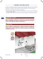
Page 15: ... The power supply unit must not be in direct contact with the ground or humid environments INSTALLATION AREA When connecting the electricity it is necessary that a power outlet is positioned next to the installation area Make sure that the connection to the mains power conforms to the applicable regulations and standards It is recommended to install the unit in a cabinet for electric components fo...

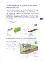
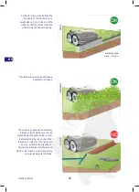
Page 16: ...e garden must be suitably checked and adjusted so that the robot has enough space for recognising when there is no grass Carefully follow the above points for the correct and safe use of the robot minum width of 25 cm 9 8 inc OK PAVEMENT The robot requires a area of at least 25 cm 9 84 inches without grass to stop safely and change direction Pavements or kerbs must be at least 25 cm wide 9 84 in K...

Page 17: ... or adequate paving The work area can also be effectively delimited by hedges HOLES NO The work area cannot be delimited by ditches or holes which must not be present inside the grassy area to mow Before starting the robot check that there are no objects on the lawn such as toys small stones branches or sprinklers protruding from the ground which could impede correct functioning or cause damage to...

Page 18: ...to delimit the perimeter of these elements with paving walls or barriers to prevent the malfunctioning of the robot Elements trees poles etc ref fig obstacles which do not impede the robot s normal functioning do not require delimiting Do not under any circumstance leave areas which have not been delimited by barriers inside the work area as these will prevent the robot from functioning properly r...

Page 19: ...echnical Specifications page 9 Areas with steeper slopes or that are incompatible with the correct functioning of the robot see following points cannot be mowed Steeper slopes must be delimited The sensors of the robot allow detecting slopes which cannot be tackled The direction is reversed in order to prevent the robot from tipping over or malfunctioning Despite this as a further protection it is...

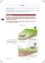
Page 20: ...d to mark the boundary of flower strips which gently descend onto the grassy surface are also interpreted as slope changes DOWNWARD SLOPE OK included between 0 and 15 15 OK UPWARD SLOPE 15 included between 0 and 15 The robot can tackle height differences with slopes of up to 15 if they slope down suddenly Areas with slopes greater than those admissible cannot be mowed with the robot Check the robo...

Page 21: ... 50 cm 19 6 inc wall height less than 9 cm 3 5 inc land width less than 70 cm 27 5 inc no presence of non grassy ground NO WATER The figure above shows a work area which has been correctly delimited for the correct functioning of the robot The figure above shows a work area where the robot s operating areas have not been correctly delimited thus preventing it from functioning properly the foliage ...

Page 22: ...g the red symbol Once connected the robot automatically turns on to show the recharging level of the batteries see meaning of LED combination on page 25 At the end of the charging First disconnect the red cable and then the black one Press the OFF key On first recharge the batteries must remain connected for at least 24 hours The figure shows the correct installation of the robot s recharging zone...

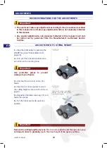
Page 23: ... days in order to gradually reach the ideal height of the grassy surface INSERTING SPACERS WITH SCREWS INSERTING BLADE WITH SCREWS check that the slope of the blade with the robot in the start position is facing downwards 1 Stop the robot safely by pressing the ON OFF key see Robot safety stop page 26 2 Turn over the robot and position it so as not to ruin the covering hood 3 Unscrew the screws to...

Page 24: ... lawn mower on or off B START STOP Press to start or stop place in stand by the lawn mower When using the robot for the first time it is recommended to carefully read the entire manual and to fully understand it especially the safety information Only use the robot for the uses intended by the Manufacturer and do not tamper with any device to obtain different performances Important ...

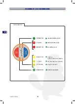
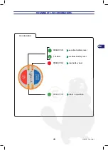
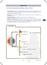
Page 25: ...NS STEADY ON in pause in pause due to low battery 1 FLASH the lawn has been mowed 2 FLASHES no grass present IN OPERATION STEADY ON low battery level 1 STEADY ON excellent battery level STEADY ON robot in operation 1 2 1 FLASH medium battery level ...

Page 26: ...25 User s manual EN MEANING OF LED COMBINATIONS RECHARGING STEADY ON low battery level STEADY ON excellent battery level 1 FLASH medium battery level 1 STEADY ON robot in operation ...

Page 27: ...etre 40 0 5 in from any obstacle Press the OFF ON key and wait a few seconds for the robot to turn on completely 6 Press START STOP key to start the robot 7 Once the robot has stopped due to the reasons described in the chapter Robot Stop activate the safety stop and reposition the robot inside the power supply unit for recharging see page 21 ROBOT SAFETY STOP When using the robot it may become ne...

Page 28: ... presence of grass for an extended period Discharged batteries The batteries have used up their operating capacity Batteries in protection When the batteries have reached a capacity which is lower than the level of the discharged batteries the robot completely turns off without displaying any indication In this case connect the robot to the recharger The robot will not turn on immediately as norma...

Page 29: ...utlet 2 Reactivate the main electrical power supply 3 Place the button of the power supply unit on ON 4 Recharge the batteries of the robot for at least 12 hours 5 Once the recharging has been completed operate the robot normally BATTERY RECHARGE AFTER PROLONGED INACTIVITY Position the robot next to the recharging zone Check that the recharging knobs on the wheels are clean 1 Check that the power ...

Page 30: ...e robot make sure the area to mow is clear of people in particular children the elderly or disabled people and domestic animals to prevent safety risks To prevent this risk it is recommended to program the production activity of the robot in suitable times Do not start the robot in case of rain or strong humidity The best results are obtained in the middle of the day Frequency Part Type of mainten...

Page 31: ...nd wheels and remove any deposits and or residuals that may obstruct the correct functioning of the robot 6 To remove any deposits and or other residuals from the blade use a suitable brush 7 Clean the battery recharge knobs and remove any oxidations or residuals caused by electric contacts with a dry cloth and if necessary with fine abrasive paper 8 Check the level of sharpness of the cutting bla...

Page 32: ...ngulfed by residuals tapes ropes plastic fragments etc Stop the robot safely see Robot safety stop page 26 Use protective gloves to avoid the risk of cutting your hands Remove the cause of the flood from the blade The robot was started too close to obstacles less than 1 m 40 in away or in the presence of unexpected obstacles fallen branches forgotten objects etc Stop the robot safely see Robot saf...

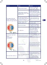
Page 33: ...eplace the batteries with original spare parts The batteries do not recharge completely Clean and remove any oxidizations from the contact points of the batteries see Robot Cleaning page 30 Recharge the batteries for at least 12 hours The wheel motor error LED flashes 1 or 2 flashes of the green ON LED Uneven ground or ground with obstacles that impede movement Check that the lawn to mow is even a...

Page 34: ...cles and restart the robot Electric motor failure Have the motor repaired or replaced by the nearest authorised service centre Too high grass Increase the cutting height see Cutting height adjustment page 22 Carry out a preliminary cutting of the area with a normal lawnmower The tip over error LED flashes 4 LEDs flashing consecutively Ground with too much slope or with undefined borders Check the ...

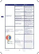
Page 35: ...heck that the power supply unit is correctly connected to the power outlet Fuse interrupted Have the fuse replaced by the nearest authorised service centre ERROR SIGNALS 1 FLASH right motor error 1 2 FLASHES left motor error 2 3 FLASHES blade error 3 4 FLASHES tip over error 4 ...

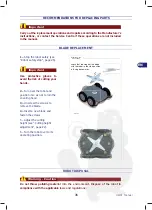
Page 36: ...er to its operating position ROBOT DISPOSAL Do not throw polluting material into the environment Dispose of the robot in compliance with the applicable laws and regulations BLADE 2 Carry out the replacement operations and repairs according to the Manufacturer s instructions or contact the Service Centre if these operations are not included in the manual INSERTING BLADE WITH SCREWS check that the s...

Page 37: ......

Reviews: