ENG
| Instruction Manual
REQUIREMENTS
LK 422 Manifold Shunt 2.0 should be used in systems with a primary
supply temperature that is weather dependent. Check the settings
of the temperature limiter control.
The heating system must before assembly be flushed through and
must not contain any impurities or additives that can damage the
LK 422 Manifold Shunt 2.0. Max. 50% glycol or 30% ethanol mix.
NOTE!
Be aware of the fire hazard when mixing with ethanol and the
resilience of other components to the ethanol mix.
During assembly, ensure that the pump axle is horizontal and that
any valve actuators are not placed below the control valve.
When choosing a suitable location for installation,pay attention to
any possible structure-borne noise.
ASSEMBLY
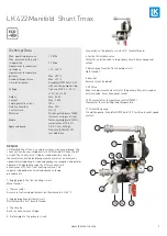
The shunt unit can be mounted
directly to LK Manifolds from
both the right and left. To fa-
cilitate this, two Manifold Supply
Pipes are supplied, where the
shorter is used for right mount-
ing, see illustration.
When fitting from the left,
move the thermometers to the opposite side of the shunt unit and
use the longer pipe.
BY-PASS
LK 422 Fördelarshunt 2.0 is fitted with an automatic speed controlled
pump, which means the manifold does not require a mechanical By-
Pass.
LK Systems AB, Box 66, 161 26 Bromma | www.lksystems.se
Förutsättningar
När shuntgruppen monteras i handmanövrerat
utförande ska den installeras i system med ute-
temperaturkompenserad primär framlednings-
temperatur. Kontrollera temperaturbegränsarens
inställning. I annat fall rekommenderas att shunt-
gruppen utrustas med LK Styr v.3 för optimerad
drift och låg energiförbrukning.
Värmesystemet ska före montage vara renspolat
och får ej innehålla föroreningar eller tillsatser
som kan skada LK Fördelarshunt VS2. Max 50 %
glykol- eller 30% etanolinblandning.
OBS!
Beakta brandrisk vid etanolinblandning samt övriga kom-
ponenters tålighet mot etanolinblandning.
Vid montage tillse att pumpens axel blir horison-
tell och så att eventuellt ventilställdon inte blir
placerat under styrventilen.
Vid val av installationsplats beakta ev. stomljud.
Montering
Shuntgruppen kan monteras i både höger- och
vänsterutförande direkt mot LK Värmekretsför-
delare. Detta möjliggörs då det fi nns bipackat två
stycken tilloppsrör där det kortare används vid
högermontage, se bild ovan.
Vid vänstermontage fl yttas termometrarna till
motsatta sidan av shuntgruppen och det längre
tilloppsröret används.
By-Pass
Shuntgruppen är utrustad med automatisk varv-
talsreglerad pump vilket innebär att By-Pass inte
behöver monteras på värmekretsfördelaren.
Placering i LK Installationsskåp
Shuntgruppen kan monteras tillsammans med
LK Värmekretsfördelare i särskilt framtagna skåp
i enlighet med branschpraxis. Skåpen har tät bot-
ten med rörgenomföringar av gummi. Botten är
försedd med dränagestos vilket gör att ev. läcka-
gevatten kan dräneras till inspektionsbar plats.
LK Shuntskåp VS2
LK Shuntskåp VS2 kan monteras i vägg resp.
utanpå vägg. Vid montage i vägg används Ram/
lucka GV INB som täcker håltagningen i väggen.
Vid montage utanpå vägg används Ram/lucka
GV UTV som slutar kant i kant med skåpet. Kom-
plettera med LK Sockel vilken döljer rören mel-
lan skåp och golv vid det utvändiga montaget.
• LK Shuntskåp VS2 800 rymmer LK Förde-
larshunt VS2 och LK Värmekretsfördelare RF
2-7.
• LK Shuntskåp VS2 1050 rymmer LK Förde-
larshunt VS2 och LK Värmekretsfördelare RF
2-12.
OBS!
Vid montage av LK Shuntskåp VS2 i vägg krävs en minsta
väggregeltjocklek på 95 mm med 13 mm väggbeklädnad.
Shuntgruppen placeras till höger om fördelaren, se instruk-
tion LK Shuntskåp VS2.
SE.33.C.184.161228
Monteringsanvisning | LK Fördelarshunt VS2
3 (10)
Svenska
CIRCULATION PUMP
The circulation pump has automatic speed control, which reduces
power consumption and gives a quieter operation as the pump ad-
justs the flow according to the requirements of the system. A cast
arrow on the pump housing indicates the direction of the flow. For un-
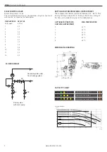
derfloor heating it is recommended that the pump is set to constant
pressure control, see capacity diagram below. Select the constant
pressure curve which best matches the design system flow and pres-
sure drop, choose between the curve CONST. PRESS. CURVE 1, 2 or 3.
NOTE!
Ensure that the pump never runs dry and the system is well vented
Before use.
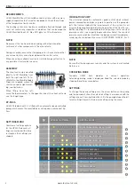
OPERATING MODE
Grundfos UPM3 Auto indicates in normal operation.
Selected operating mode is displayed. Read the selected mode by
studying the settings menu below.
SETTINGS
To change the pump setting press the arrow button on the pump,
and the pump will show the selected setting in accordance with the
settings menu. Pressing the button shifts the pump between the dif-
ferent settings. Adjust to the desired setting using the menu.
SETTINGS MENU
CONSTANT PRESSURE 1
CONSTANT PRESSURE 2
CONSTANT PRESSURE 3
MAX
OPERATING PANEL
CONTROL MODE
0
PROPORTIONAL PRESSURE AUTO ADAPT
1
CONSTANT PRESSURE AUTO ADAPT
2
PROPORTIONAL PRESSURE 1
3
PROPORTIONAL PRESSURE 2
4
PROPORTIONAL PRESSURE 3 - MAX
5
CONSTANT PRESSURE 1
6
CONSTANT PRESSURE 2
7
CONSTANT PRESSURE 3 MAX
8
CONSTANT CURVE 1
9
CONSTANT CURVE 2
10
CONSTANT CURVE 3 MAX
OPERAT
AA ING PA
PP NEL
CONTROL MODE
0
PROPORTIONAL PRESSURE AUTO ADAPT
1
CONSTANT PRESS
TT
URE AUTO ADAPT
2
PROPORTIONAL PRESSURE 1
3
PROPORTIONAL PRESSURE 2
4
PROPORTIONAL PRESSURE 3 - MAX
8
CONSTANT C
TT
URVE 1
9
CONSTANT C
TT
URVE 2
10
CONSTANT C
TT
URVE 3 MAX
Overview of settings options
for the UPM3. Relevant set-
tings are marked with a blue
rectangle, other settings are
shaded.
2
www.lkarmatur.com


