background image

11 (15)

EN.33.C.94.1702

Assembly instructions | LK Electric Boiler 11-n

Steady illumination  Normal operation 
One long + one 

short flash 

Delay in connection after a power outage limits output adjustment. 

One long + two 

short flashes 

Loading relay, room thermostat or some other external control device limits output adjustment. 

One long + three 

short flashes 

A. Overheating (maximum safe) temperature

Connected output becomes disconnected immediately when the temperature exceeds set point value by 

more than 5 °C. Reconnection takes place when temperature falls below overheating (maximum safe) 

temperature.

B. Malfunction at boiler temperature sensor

Output is not switched on despite temperature being below set point value. Replace sensor. Acknow-

ledge alarm by keeping boiler switched off for 10 seconds, turn main switch to position 0. 

One long + four 

short flashes 

Remote control activated. 

Rapid flashes 

By-passing of the connection delay: SNABB (Quick) button, item 13 in wiring diagram, keep button 

pressed down until status indicator is illuminated steadily. 

Loss of pressure 

No voltage or selector in position: 

UTK panel

15

14

13

11

12

The panel is viewable once the boiler’s top support has been taken off and the automation cabinet’s control 

panel has been folded out.

11. 

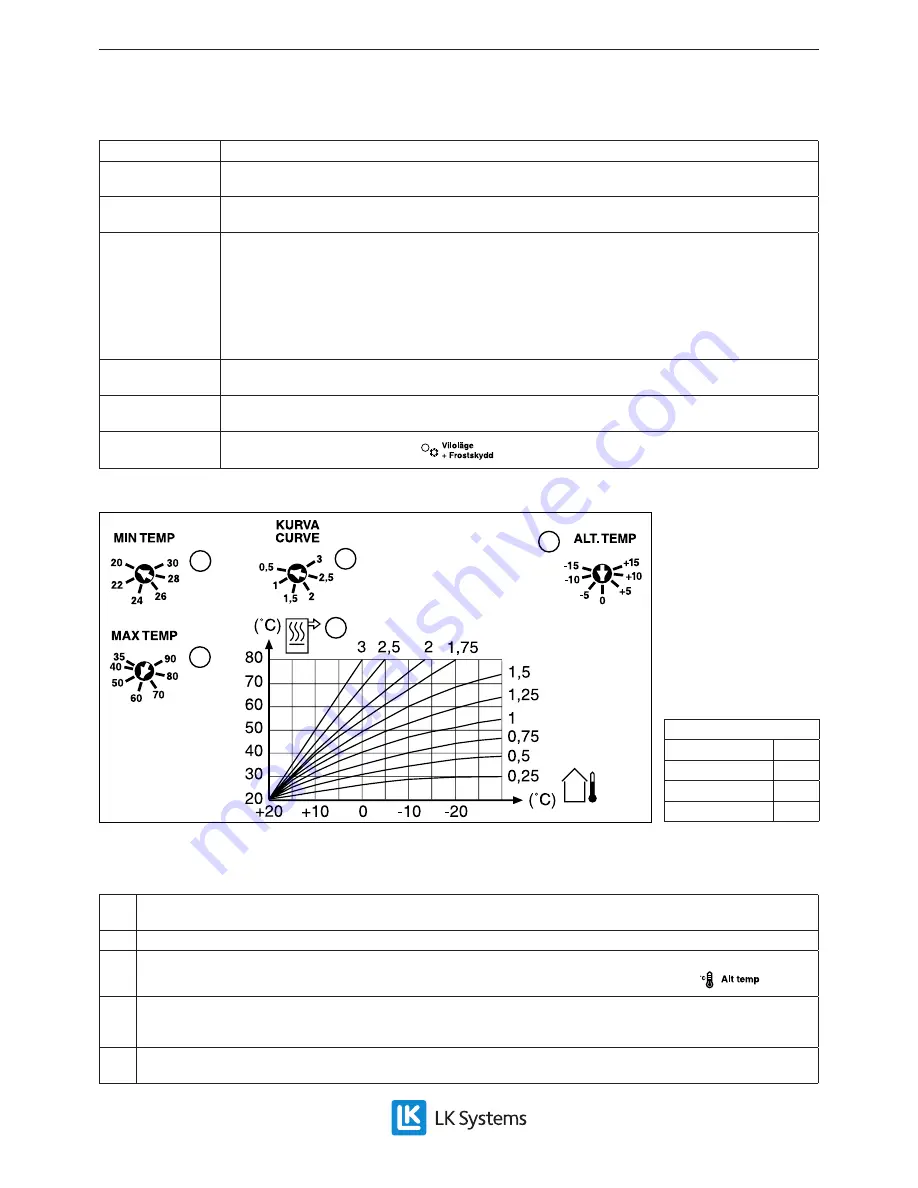
Temperature diagram: This shows the dependence of the temperature of the flow water on the selected graph and the 

outside temperature. 

12.  Maximum temperature: Highest allowed temperature, 60 °C, (not adjustable). 
13.  Alternative temperature: The temperature of the outgoing water can be increased/decreased ±15 °C in relation to the 

normal temperature. Adjustments are implemented by using the selector switch, see item 5 above. 

14.  Water temperature flow rates used as the output values available on the graph are used in the floor heating calcula-

tions. If these values are not available, use graph 1 for under floor heating systems laid over a timber sub-floors. If the 

loops of tubing are embedded in concrete, use a lower graph, e.g. 0.75. 

15.  Minimum temperature: Lowest allowed temperature of flow water. If there is no particular requirement, do the installa-

tion for a temperature of 20 °C. 

Supply settings:

Min. temp. 

20 ºC 

Graph 

Alternative temp.  -5 ºC 
Max temp. 

60 ºC 

Summary of Contents for 11-n

Page 1: ...erflow valve safety valve device to pre vent overheating if low flow rates it activa tes maximum safe temperature protection Circulation pump Grundfos UPM3 15 40 Enclosure concealing pipe connections...

Page 2: ...tridge 25 Skirt concealing pipe connections 13 14 15 12 23 17 18 22 3 19 25 1 2 5 4 8 7 6 9 16 18 20 17 11 14 13 24 12 22 21 10 Ben mning 1 Safety valve 2 5 bar female 2 Automatic air bleeding valve m...

Page 3: ...stallation The space between the floor and the boiler base must be at least 600 mm to allow electric cartrid ges to be replaced The connection of the boiler and the heating sys tem must be in accordan...

Page 4: ...ESSURE CURVE 3 CONST CURVE KURVA 1 CONST CURVE KURVA 2 CONST CURVE KURVA 3 CONST CURVE KURVA 4 If the button is depressed for 2 sec the pump switches to setup mode and the LEDs flash In setup mode any...

Page 5: ...d To avoid this an overflow valve is built in ensuring flow though the boiler If the pressure resistance of the heating system ex ceeds the overpressure flow problems can arise in the heating system F...

Page 6: ...from the fuses and must be protected Connection is made to the base of the circuit board using high current insulated cable minimum 0 75 mm2 The earth grounding is connected using terminal 4 The trans...

Page 7: ...acity corresponds to 7 9 kW When applying voltage based control 0 10V DC 10V is needed for connecting five levels The same applies to the voltage signal for con nected capacity Delay in connection fol...

Page 8: ...put Groups 1 and 2 as well as 3 x 2 1 kW for Output Group 3 Wiring diagram 1 2 3 4 5 6 7 8 9 10 11 12 13 14 18 15 19 19 17 16 BLACK BLACK BLACK BLACK WHITE WHITE WHITE WHITE WHITE WHITE BROWN BROWN BR...

Page 9: ...11 kW Fuse Fuse Fuse Fuse Fuse Output level Output Cur rent L1 Cur rent L2 Cur rent L3 Output group kW A A A 1 15 1 6 3 9 3 9 0 1 2 30 3 1 3 9 3 9 7 8 2 3 45 4 7 6 8 6 8 6 8 1 2 4 55 6 3 9 1 9 1 9 1 3...

Page 10: ...ning main switch to position O if the purpose is to switch off the boiler Heating system needs to be filled with water The circulation pump is set in motion and protection against freezing is activate...

Page 11: ...atus indicator is illuminated steadily Loss of pressure No voltage or selector in position UTK panel 15 14 13 11 12 The panel is viewable once the boiler s top support has been taken off and the autom...

Page 12: ...f the system s pressure drops and does not rise fill it up with water until the pressure gauge shows approx 2 bar Repeated problems in main taining the pressure may be an indication of a leak in the s...

Page 13: ...s indicated by the flashing of the status indicator see item 10 and Control panel Overheating maximum safe temperature protection The electric boiler s overheating maximum safe temperature protection...

Page 14: ...ion has been triggered If overheating maximum safe temperature protection function has been triggered check functioning of circulation pump and valves Reset by pressing overheating maximum safe temper...

Page 15: ...ditional power consumption In standby mode PSB 0 003 kW Standby heat loss Pstby 0 022 kW Outside temperature compensator UTK E Class II 2 contribution to Season medium efficiency Recycling After disma...

Reviews: