2000
3.
S
TARTING GOCATOR
NOTE: Gocator must be connected to a host computer in order to launch the user interface and setup the sensor.
Gocator sensors are configured by connecting with a web browser.
The user interface is supported with FireFox 3.5+, Chrome 4.0+, & Internet Explorer 8.0+. (Use FireFox or Chrome for optimal
performance.) The Adobe Flash browser plugin version 10.0+ must be installed.
T
ROUBLESHOOTING
PROBLEM
SUGGESTED RESOLUTION
Mechanical / Environmental
The sensor is warm.
• It is normal for a sensor to be warm when powered on.
Connection
When connecting with a web browser, the
sensor is not found (page does not load).
• Verify the sensor power is on. This will be indicated by an illuminated POWER LED.
• Verify the cable from the sensor’s LAN connector is plugged into the Ethernet port on the client computer.
• Verify that the client computer’s network settings are properly configured. Refer to the Connecting to a New
•
Sensor section in the Gocator user manual or to your computer’s documentation on configuring a network adapter.
• Download 14405-x.x.x.x_software_go2_tools.zip from the downloads area of LMI’s website at www.lmi3D.com
.
Unzip and run the Sensor Discovery Tool [bin>win32>kDiscovery.exe] to verify that the sensor has the correct network settings.
When attempting to log in, the password is not
accepted.
• Download 14405-x.x.x.x_software_go2_tools.zip from from the downloads area of LMI’s website at www.lmi3D.com
.
Unzip and run the Sensor Discovery Tool [bin>win32>kDiscovery.exe] to discover the sensor on the network and restore default settings.
NOTE: Using the Sensor Discovery tool will reset your configuration settings to default - these settings can be recovered from the backup
files if previously saved.
Laser Profiling
When the Play button is pressed, the sensor
does not emit laser light.
• Ensure that the decal covering the laser emitter window, normally affixed to new sensors, has been removed.
• Verify that the LASER LED on the Gocator is illuminated, if not, the laser safety input signal is off. Refer to
•
Laser Safety Input Section in the Gocator user manual to determine the correct solution for your application.
• The exposure setting may be too low. Refer to the Exposure section in the Gocator User Manual for more information
•
on configuring exposure time.
The sensor emits laser light, but the
Range Indicator does not illuminate and/or
points are not displayed in the Profile Viewer.
• Verify that the measurement target is within the sensor’s field of view and measurement range.
The RANGE LED on the Gocator will illuminate when the target is in range.
• Check that the exposure time is set to a reasonable level. Refer to the Exposure section in the Gocator User Manual
•
for more information on configuring exposure time.
The sensor CPU level is near 100%.
• Review the active measurements and eliminate any that are unnecessary measurements.
• Consider reducing the trigger speed.
• Consider reducing the laser profiling resolution.
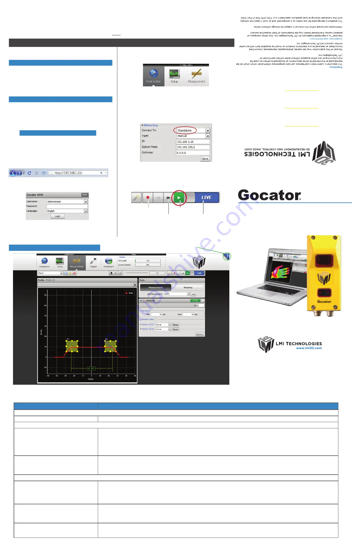
Once connected to the Gocator, click the Help icon to
view the User Manual, update firmware, or download SDK
An example of the user interface in use
Worldwide
Email:
support@lmi3D.c
om
Web:
ww
w.lmi3D
.com
North America
Phone:
+1 604 636 10
11
Fax:
+1 604 516 8368
Europe
Phone:
+31 45 850 7000
Fax:
+31 45 574 2500
Quick Start Guide
In Windows 7
•Open the Control Panel>Network and Sharing Center>Change Adapter
Settings.
•Right-click desired network connection, then click Properties.
•On the Networking tab, click Internet Protocol Version 4 (TCP/IPv4),
then click Properties.
•Select “Use the following IP address” option.
•Enter IP Address “192.168.1.5” and Subnet Mask “255.255.255.0”, then
click OK.
In Mac OS X 10.6
•Open the Network Pane in System Preferences and select Ethernet.
•Set Configure to “Manually”.
•Enter IP Address “192.168.1.5” and Subnet Mask “255.255.255.0”, then
click Apply.
B. R
UNNING GOCATOR
A. L
AUNCHING THE INTERFACE
Open a web browser and enter the sensor address
Select language of choice
Step 2
Step 3
Step 1
The Administrator password is initially blank. Press the Login
button to connect
Step 4
Gocator is shipped with the following default network
configuration
Setting
Default
DCHP
Disabled
IP Address
192.168.1.10
Subnet Mask
255.255.255.0
Gateway
0.0.0.0
Step 1
Select the Connection Page
Change network setting on host computer
Step 3
Ensure data source is set to LIVE and the Laser Safety switch
is enabled or the Laser Safety input is high. Press the PLAY
button in the toolbar to start the sensor (a laser line should
now be visible)
Step 4
Move target into the laser plane and measure!
For the user manual, CAD drawings, firmware release notes, SDK, and
more, go to www.lmi3D.com/downloads
Step 2
Select what the Gocator will be connected to
RECORD
SNAPSHOT
START
DATA SOURCE
Single Sensor:
Select Standalone
Using Master 400:
Select Master 400
Using Master 800:
Select Master 800
Using Master 1200:
Select Master 1200
Using Master 2400:
Select Master 2400
15161-1.2-Manual_Quickstart_Gocator-2000-Series
©2014 LMI T
echnologies Inc. All rights reserv
ed.


