background image

121

APPENDIX

Important

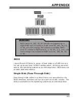
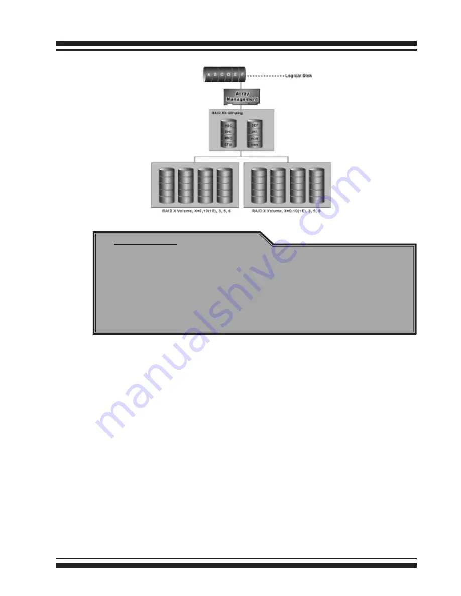
RAID level 00, 100, 30, 50 and 60 can support up to 

eight RAID set. If volume is RAID level 00, 100, 30, 50, 

or 60, you can’t change the volume to another RAID 

level. If volume is RAID level 0, 1, 10(1E), 3, 5, or 6, you 

can’t change the volume to RAID level 00, 100, 30, 50, 

or 60.

JBOD

(Just a Bunch Of Disks) A group of hard disks in a RAID box are 

not set up as any type of RAID configuration. All drives are avail-

able to the operating system as an individual disk. JBOD does not 

provide data redundancy.

Single Disk (Pass-Through Disk)

Pass through disk refers to a drive that is not controlled by the 

RAID firmware and thus can not be a part of a RAID volume. The 

drive is available to the operating system as an individual disk.

Summary of Contents for ThunderBox 800

Page 1: ...ThunderBox 800 Thunderbolt 2 to 6Gb s SAS RAID Storage User Manual Version 1 0 Issue Date June 2014 Thunderbolt Product...

Page 2: ...ese limits are designed to provide reasonable protection against in terference in a residential installation This equipment generates uses and can radiate radio frequency energy and if not installed a...

Page 3: ...e MRAID Software 22 2 5 2 2 Configure RAID Volumes 26 2 5 2 3 Format RAID Volumes 29 2 5 2 4 Make A Bootable RAID Volume 31 2 5 2 5 Unmounting RAID Volumes 31 2 5 3 Windows Users 32 2 5 3 1 Install th...

Page 4: ...Volume Support 57 Initialization Mode 58 Stripe Size 58 Cache Mode 59 Volume Write Protection 59 Full Volume Encryption 59 Tagged Command Queuing 60 SCSI Channel SCSI ID SCSI Lun 60 4 6 2 Create Raid3...

Page 5: ...che Mode 74 Write Same For Initialization 74 Hot Plugged Disk For Rebuilding 74 Disk Capacity Truncation Mode 75 Smart Option For HDD 75 Smart Polling Interval 76 4 8 2 Advanced Configuration 76 TLER...

Page 6: ...sword 87 4 8 12 Update Firmware 87 4 9 Information 88 4 9 1 Raid Set Hierarchy 88 4 9 2 SAS Chip Information 88 4 9 3 System Information 89 4 9 4 Hardware Monitor 89 Appendix A 90 Upgrading Flash ROM...

Page 7: ...t Spares 110 Hot Swap Disk Drive Support 111 Auto Declare Hot Spare 111 Auto Rebuilding 112 Adjustable Rebuild Priority 112 High Reliability 113 Hard Drive Failure Prediction 113 Auto Reassign Sector...

Page 8: ...gle Thun derbolt connection to their host computer ThunderBox 800 can meet the demand of users when working with rich ultrahigh resolution media through Thunderbolt 2 interface Unparalleled Performanc...

Page 9: ...that protects all data in cache memory in the event of unexpected power outage Board level hardware encryption manages any kinds of drives attached to ThunderBox 800 without impacting the performance...

Page 10: ...ipe size migration Support global hot spare and local hot spare Instant availability and background initialization Advanced configuration for smooth data streaming Disk scrubbing array verify scheduli...

Page 11: ...in the event of unexpected power outage Intelligent power On Off function Turn ThunderBox 800 power in unison with the host computer power status for data integrity Front Panel LCD and Buttons Easy ac...

Page 12: ...t it for dam age If the ThunderBox 800 appears damaged or if any items of the contents listed below are missing or damaged please contact your dealer or distributor immediately Checklist 1 x ThunderBo...

Page 13: ...on Step 3 Configure RAID Volumes Chapter 2 5 2 2 1 Double click on the MRAID icon on the desktop 2 Double click on the ArcHTTP64 3 Locate Web Management and launch the McRAID storage manager 4 Login U...

Page 14: ...the McRAID storage manager 4 Login User Name admin and the Password 0000 5 Click on the Quick Create to configure the volume 6 Follow the on screen steps to complete the configuration Step 4 Format RA...

Page 15: ...Thunderbolt Port1 5 Thunderbolt Port2 6 Thunderbolt Port1 Link LED 7 Thunderbolt Port2 Link LED 8 System Fan1 9 LAN Port For McRAID Web Manager 10 Reset Button 11 System Fan2 12 Power Connector 13 Po...

Page 16: ...he activity LED is lit there is I O acti vity on that disk drive 2 When the LED is not lit there is no activity on that disk drive N A 2 Fault Link LED Red Green 1 When the fault LED is lit there is n...

Page 17: ...y of the front panel LED 2 4 3 Thunderbolt Port LED Indicators Figure 2 3 Thunderbolt Ports LED Panel LED Normal Status Problem Indication 1 Power LED Green Solid green when power on Unlit when power...

Page 18: ...e contained in its individual hole on the disk carrier Each drive is hot pluggable allowing you to remove and insert drives without shutting down your RAID storage Installation in this section describ...

Page 19: ...Connecting RAID Storage to Thunderbolt Ports Thunderbolt connectors are provided on the back of the Thunder Box 800 for connecting the array to Thunderbolt host and next Thunderbolt devices There are...

Page 20: ...ogies A single Thunderbolt technology daisy chain can have seven devices including the computer Connect the cable to one of the interface ports on the back of your ThunderBox 800 and to your Thunderbo...

Page 21: ...directly connected to the 10 100Mbit RJ45 LAN port Connect LAN port of the ThunderBox 800 using the in cluded Ethernet cable and then to a LAN port or LAN switch Step 4 Connecting RAID Storage Power T...

Page 22: ...et up RAID volumes 2 5 2 Mac Users 2 5 2 1 Install the MRAID Software This section describes detailed instructions for installing the Areca Mac driver utility for the ThunderBox 800 on your Apple Thun...

Page 23: ...stall_mraid on the Finder The MRAID Installer opens Click on the Next button to begin the installation 4 The MRAID Installer opens Click on the Next button to begin the installation 5 On the Choose In...

Page 24: ...ctionality available in MRAID storage manager through a Command Line Interface You can set up and manage RAID storage inline CLI performs many tasks at the command line You can download CLI manual fro...

Page 25: ...NSTALLATION 25 8 A program bar appears that measures the progress of the driver installation 9 When this screen shows you have completed the driver installation and click on the Next button to continu...

Page 26: ...ID storage manager by ArcHTTP and CLI utility If you have not yet installed the hardware plea se follow the 2 5 1 Physically Install RAID Storage and Drives section to install it Otherwise to begin th...

Page 27: ...er When you double click on the ArcHTTP64 it shows all RAID storages available on the system and create an individual RAID storage icon located on left column of the ArcHTTP Con figurations screen Loc...

Page 28: ...anager Other wise to begin using the ThunderBox 800 right away go on the next Format the Volume section to begin the formatting procedure Method 2 McRAID Storage Manager Through LAN port User can remo...

Page 29: ...t User Name is admin and the Password is 0000 The LCD initial screen is shown below 2 5 2 3 Format RAID Volumes After the volume set is ready for system accesses it needs to be partitioned formatted a...

Page 30: ...Each partition will appear as a separate drive on your computer 3 Specify your Partition Information Option setting and click on the Apply button 4 When a message asks you to confirm you want to parti...

Page 31: ...see the option to choose the flash drive to boot from 4 Follow the on screen prompts to complete Areca Volume Upgrade and Clean Install of OS X Mavericks Power up the Intel based Mac and Areca volume...

Page 32: ...or Custom to install special components Follow the steps below to install the driver utility for Windows 1 Download the install_mraid installer from the website at http www areca com tw support s_thu...

Page 33: ...screen appears read and agree to the license information then let the InstallShield Wizard guide you through the installation process 6 On the Setup Type screen use the settings to specify these thin...

Page 34: ...Box 800 ArcHTTP has to be installed for GUI RAID console McRAID storage manager to run It also runs as a service or daemon in the background that allows capturing of events for mail and SNMP traps not...

Page 35: ...t measures the progress of the driver installation When this screen completes you have completed the MRAID installation If you have no ThunderBox 800 unit yet connected or powered on a MRAID Installer...

Page 36: ...or you to start up the McRAID storage manager by ArcHTTP and CLI utility If you have not yet installed the hardware please follow the 2 5 1 Physically Install RAID Storage and Drives section to instal...

Page 37: ...ams MRAID ArcHTTP When you double click on the ArcHTTP64 it shows all RAID storages available on the system and create an individual RAID storage icon located on left column of the ArcHTTP Con figurat...

Page 38: ...web brows ers To configure ThunderBox 800 using a LAN port you need to know its IP address The default IP address will be shown on the LCD initial screen Launch your web browser based McRAID storage m...

Page 39: ...Scroll down to the bottom of the middle pane Windows will display a list of new drives attached to your system with a label such as Disk 1 or Disk 2 etc 4 Right click on the drive you want to partiti...

Page 40: ...ox 800 from a Windows system 1 Click on the Safely Remove Hardware and Eject Media icon in the notification area at the lower right hand side of your screen and then in the list of devices choose the...

Page 41: ...n is for you to start up the ArcHTTP utility When you click the ArcHTTP it shows all RAID storages available on the system and System Function on left column of the ArcHTTP Configurations screen The A...

Page 42: ...n an alert is detected To set up your mail servers click on the the Mail Configuration link The SMTP Server Configurations allows you to define settings for your mail server This setup screen is shown...

Page 43: ...er s e mail address This is the address you want the e mail alerts sent to Ex admin areca com tw According to your requirement set the corresponding event level Disable Event Notification No event not...

Page 44: ...community name into its request otherwise the SNMP agent will deny access to the system Most network devices use public as default of their community names This value is case sensitive 3 SNMP Trap Not...

Page 45: ...can Device function is a procedure which forces the ArcHTTP to rescan the targets to allow a missed RAID storage to be added Collect Support Data Areca has added the Collect Support Data option on the...

Page 46: ...ccessed through the in band Thunderbolt bus or out of band onboard LAN port The in band Thunderbolt bus method can launch the web browser based McRAID storage manager via ArcHTTP proxy server The firm...

Page 47: ...MRAID icon show ing on your Desktop or Start menu This icon is for you to start up the ArcHTTP launch the McRAID storage manager and CLI utility When you click on the ArcHTTP from MRAID icon it shows...

Page 48: ...McRAID storage manager in the firmware User can re mote manage the Thunderbolt RAID storage without adding any user specific software platform independent via standard web browsers directly connected...

Page 49: ...t configuration which is based on the number of physical disks installed it can modify the volume set Capacity Raid Level and Stripe Size Raid Set Functions Create a customized RAID set Volume Set Fun...

Page 50: ...nfiguration can provide full control of the RAID set settings but it will take longer to complete than the Quick Volume Raid Setup configuration Select the Raid Set Function to manually configure the...

Page 51: ...roaming this raidset to Areca SATA RAID controllers The SATA RAID controller is designed to support up to 16 volumes only You have to use Max 16 volumes on the raidset mode if you plan to roam this ra...

Page 52: ...nsion screen appears 2 Select the target RAID set by clicking on the appropriate radio button Select the target disk by clicking on the appropriate check box 3 Click on the Submit button to start the...

Page 53: ...ing able to unmount and remount a multi disk volume All Hdds of the selected RAID set will be put into offline state spun down and fault LED in fast blinking mode User can remove those Hdds and insert...

Page 54: ...ivate Raid Set link A Select The Raid Set To Activate screen is dis played showing all RAID sets existing on the current controller Click the RAID set number to activate in the select column Click on...

Page 55: ...elete Hot Spare Select the target hot spare disk to delete by clicking on the ap propriate check box Click the Confirm The Operation check box and click the Submit button on the screen to delete the h...

Page 56: ...t on the RAID set will have its data spread evenly across all the disks in the RAID set The following is the volume set features for the RAID storage 1 Volume sets of different RAID levels may coexist...

Page 57: ...tion Mode Strip Size Cache Mode Tagged Command Queuing and SCSI Channel SCSI ID SCSI Lun Volume Name The default volume name will always appear as ThunderBox 800 VOL You can rename the volume set prov...

Page 58: ...Background Initialization the initialization proceeds as a background task the volume set is fully accessible for system reads and writes The operating system can instantly access to the newly create...

Page 59: ...electronic circuitry for the cryptographic engine embedded in the ROC and operating at full channel speeds The hardware encryption does not impact the performance of ThunderBox 800 RAID controller an...

Page 60: ...d to download volume key file into firmware and unlock the volume 4 Follow step 3 to unlock volume if volume locked Tagged Command Queuing The Enabled option is useful for enhancing overall system per...

Page 61: ...Raid Level Capacity Greater Two TB Volume Support Initialization Mode Stripe Size Cache Mode Tagged Command Queuing and SCSI Channel SCSI ID SCSI Lun Please refer to above section for details descript...

Page 62: ...dify Click the Submit button The following screen appears Use this option to modify the volume set configuration To modify volume set attributes move the cursor bar to the volume set at tribute menu a...

Page 63: ...expand capacity When expand volume capacity you can t modify stripe size or modify RAID level simultaneously You can expand volume capacity but can t reduce volume capacity size After volume expansion...

Page 64: ...ttempt to modify a volume s data or attributes Volume Write Protection is used primarily for customer initiated disaster recovery testing 4 6 5 Check Volume Set To check a volume set from a RAID set 1...

Page 65: ...ve A consistency check forces every block on a volume to be read and any bad blocks are marked those blocks are not used again This is criti cal and important because a bad disk block can prevent a di...

Page 66: ...to download volume key file 1 To download volume key file into the firmware move the mouse cursor to Download Volume Key file link and click it The Download Volume Encryption Key File screen appears 2...

Page 67: ...e the operating system is on a disk not controlled by the RAID firmware The user can also select the Volume Cache Mode Write Protection Tagged Command Queuing and SCSI channel SCSI_ID SCSI_LUN for thi...

Page 68: ...click the De lete Pass Through link After you complete the selection mark the check box for Confirm The Operation and click the Submit button to complete the delete action 4 7 4 Clone Disk Instead of...

Page 69: ...ing process using the existing stand by Free or Hot Spare drive to clone the source drive the Raid Set member drive The cloning pro cess percentage will be indicated in the Volume State area of the Vo...

Page 70: ...It sets a normal working disk as failed so that users can test some of the features and functions 4 7 7 Activate Failed Disk It forces the current failed disk in the system to be back online Activate...

Page 71: ...7 8 Identify Enclosure To prevent removing the wrong enclosure the selected Areca ex pander enclosure all disks fault LED indicator will light for physi cally locating the selected enclosure when the...

Page 72: ...elative indication of how much time the controller devotes to a rebuild operation The RAID storage allows the user to choose the rebuild prioity Ul traLow Low Medium and High to balance volume set acc...

Page 73: ...e Read Ahead data blocks from the disk The read ahead parameter is normal by default To modify the value you must set it from the com mand line using the Read Ahead option The normal option satisfies...

Page 74: ...drive sectors at once improving initialization time To take advantage of this feature all the drives in the unit must support Write Same command User can set the SAS And SATA SAS Only SATA Only or Dis...

Page 75: ...GB drives from differ ent vendors chances are that the capacity varies slightly For example one drive might be 123 5 GB and the other 120 GB Multiples Of 10G truncates the number under tens This make...

Page 76: ...to set the Smart Polling Interval too frequent What to use is up to the users to decide based on their applications and experimental results 4 8 2 Advanced Configuration To set the RAID storage advanc...

Page 77: ...his button and then selecting the button Normally you should not need to modify this value There are two selections either 2 retry or 3 retry Buffer Threshold This new feature there are 3 options 25 5...

Page 78: ...s cycle used in RAID controller was designed to transfer the computer data exactly it was unsuitable for the transfer of AV stream needing great band widths They are required to do some setting for th...

Page 79: ...r controller to reserve n write margin AV stream recording It is designed to eliminate the frame drop and ensure to provide the smooth and stable performance on the application Read And Discard Parity...

Page 80: ...n groups allowing the drives to come ready at the optimum time without straining the system power supply The staggered drive spin up in a multiple drive environment also avoids the extra cost of a pow...

Page 81: ...f the spindle motor to save power The values can be selected Disabled or within the range 1 to 60 minutes SATA Power Up In Standby SATA Power Up In Standby power management 2 mode PM2 is a SATA disk d...

Page 82: ...system DHCP lets a network administrator supervise and distribute IP addresses from a central point The purpose of DHCP is to provide the automatic dynamic allocation of IP client configurations for a...

Page 83: ...ntroller Telnet Port Number To manually configure the Telnet Port Number of the control ler move the cursor bar to Telnet Port Number item then reassign the default Telnet Port Number of the controlle...

Page 84: ...ArcHTTP Configuration 4 8 6 SNMP Configuration Please refer to Appendix C of SNMP Operation Installation 4 8 7 NTP Configuration The Network Time Protocol NTP is used to synchronize the time of a com...

Page 85: ...e Time Zone conveniently runs in the system tray and allows you to easily view the date and time in various locations around the world You can also quickly and easily add your own personal locations t...

Page 86: ...on to view the system events information Time Device Event Type Elapse Time and Errors The RAID storage does not have a built in real time clock The time information is the relative time from the syst...

Page 87: ...ord is used to protect the RAID storage from unauthorized entry The controller will check the password only when entering the main menu from the initial screen The RAID storage will automatically go b...

Page 88: ...reen 4 9 2 SAS Chip Information To view the RAID storage s 6Gb s SAS ROC chip information move the mouse cursor to the main menu and click on the SAS Chip Information link The RAID storage SAS Chip In...

Page 89: ...screen ap pears Use this feature to view the RAID storage s system infor mation The controller name controller firmware version Boot ROM version SAS firmware version serial number main proces sor CPU...

Page 90: ...program ARC8050MBR0 BIN Master Boot Record for supporting Dual Flash Image in the ThunderBox 800 6Gb s SAS RAID storage README TXT contains the history information of the software code change in the m...

Page 91: ...e web browser begins to download the firmware binary to the controller and start to update the flash ROM 5 After the firmware upgrade is complete a bar indicator will show Firmware Has Been Updated Su...

Page 92: ...e Interface CLI provides you to configure and manage the RAID storage components in Mac and Windows en vironment The CLI is useful in environments where a graphical user interface GUI is not available...

Page 93: ...e back cache on the RAID storage and provides power to the cache memory if it contains data not yet written to the hard drives when power failure occurs B 1 BBM Connector and Components This section p...

Page 94: ...and NH3 and secures it using round head screws 3 Connector J1 is available for the optional battery backup module Connect the BBM cable from this connector to the 12 pin J6 battery connector on the R...

Page 95: ...ours to complete 3 Set the Disk Write Cache Mode Auto if Disk Write Cache option does not set on the Auto 4 Set the volume set Cache Mode Write Back Cache B 6 Battery Functionality Test Procedure 1 Wr...

Page 96: ...J6 on the RAID storage controller 7 Secure the Round head screws into the BBM B 8 BBM Specifications Mechanical Module Dimension W x H x D 37 3 x 13 x 81 6 mm Environmental Operating Temperature Temp...

Page 97: ...in a hierarchical data structure called the Management Information Base MIB These MIBs are defined and sanctioned by various industry associations Each type of device on your network has its own spec...

Page 98: ...cation and compile the MIB description file with the SNMP management application database Before the manager application accesses the Areca RAID controller it is necessary to integrate the MIB into th...

Page 99: ...Using ArcHTTP The HTTP management software ArcHTTP runs as a service or daemon and has it automatically start the proxy for all control lers found This way the controller can be managed remotely witho...

Page 100: ...ing ArcHTTP proxy server utility to send the SNMP traps please see SNMP Traps Configuration section on chapter 3 ArcHTTP Configuration If SNMP manager requests to query the SNMP information from RAID...

Page 101: ...accesses to the SNMP agent of a particular network device Type in the com munity names of the SNMP agent Before access is granted to a request station this station must incorporate a valid com munity...

Page 102: ...nt Level Meaning Action Device Inserted Warning HDD inserted Device Removed Warning HDD removed Reading Error Warning HDD reading error Keep Watching HDD status may be it caused by noise or HDD unstab...

Page 103: ...olume deleted Modify Volume Warning Volume modified Volume Degraded Urgent Volume degraded Replace HDD Volume Failed Urgent Volume failure Failed Volume Revived Urgent Failed volume revived Abort Init...

Page 104: ...eck air flow and cooling fan of the enclosure and contact us Hdd Over Temperature Urgent Abnormally high temperature detected on Hdd over 55 degree Check air flow and cooling fan of theenclosure Fan F...

Page 105: ...us a VT100 login detected API Log In Serious a API login detected Lost Rebuilding MigrationLBA Urgent Some rebuilding migration raidset member disks missing before power on Reinserted the missing memb...

Page 106: ...the host system as a single logical device in other words a single large virtual hard disk A volume set will use a specific RAID level which will require one or more physical disks depending on the RA...

Page 107: ...lume set is protected against disk failures while initialing If using Foreground Initialization the initialization process must be completed before the vol ume set is ready for system accesses Online...

Page 108: ...on process the volume sets being expanded can be accessed by the host system In addition the volume sets with RAID level 1 10 3 5 or 6 are protected against data loss in the event of disk failure s In...

Page 109: ...d retain fault tolerance Normally expanding a RAID level 1 array would require the addition of two disks A third disk can be added to the existing RAID logical drive and the volume set can then be mig...

Page 110: ...te the additional free space within the volume into the operating system partition The operating system partition is extended to incorporate the free space so it can be used by the operat ing system w...

Page 111: ...rive To effectively use the hot spare feature you must always maintain at least one drive that is marked as a global hot spare Important The hot spare must have at least the same capacity as the drive...

Page 112: ...so that the data on the failed drive can be automatically rebuilt and so that fault tolerance can be maintained RAID controllers will automatically restart the system and rebuilding process if the sys...

Page 113: ...es available status information to RAID storage firmware that probes the drive and look at it The SMART can often predict a problem before failure occurs The controllers will recognize a SMART error c...

Page 114: ...ck is a process that verifies the integrity of redundant data To verify RAID 3 5 6 30 50 or 60 redun dancy a consistency check reads all associated data blocks computes parity reads parity and verifie...

Page 115: ...emory module Under normal operating conditions the batteries last for three years before replacement is necessary Recovery ROM RAID controller firmware is stored on the flash ROM and is ex ecuted by t...

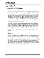
Page 116: ...d the disks physical configuration transparent to the host operating system This means that the host operating system drivers and software utilities are not affected regardless of the RAID level selec...

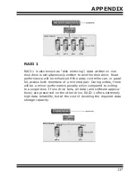
Page 117: ...f the array controller can in paral lel access both members of a mirrored pair During writes there will be a minor performance penalty when compared to writing to a single disk If one drive fails all...

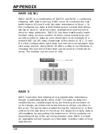
Page 118: ...ach strip is mirrored on an adjacent disk with wrap around Areca RAID 10 offers a little more flexibility in choosing the number of disks that can be used to constitute an array The number can be even...

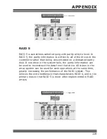
Page 119: ...edicated parity disk If one drive in the system fails the parity information can be used to reconstruct the data from that drive All drives in the array system can be used for seek operations at the s...

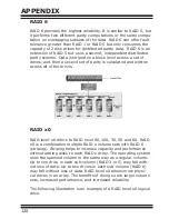
Page 120: ...and written across all of the drives RAID x0 RAID level x0 refers to RAID level 00 100 30 50 and 60 RAID x0 is a combination multiple RAID x volume sets with RAID 0 striping Striping helps to increase...

Page 121: ...00 100 30 50 or 60 JBOD Just a Bunch Of Disks A group of hard disks in a RAID box are not set up as any type of RAID configuration All drives are avail able to the operating system as an individual d...

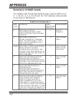
Page 122: ...disk Read request can be satisfied by data read from wither one disk or both disks 3 Up to one disk failure in each sub volume 3 Also known Bit Interleaved Parity Data and parity information is subdi...

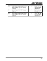
Page 123: ...g 6 Up to one disk failure in each sub volume 50 RAID 50 is a combination multiple RAID 5 volume sets with RAID 0 striping 6 Up to one disk failure in each sub volume 60 RAID 60 is a combination multi...

Reviews: