CHAPTER 4: ELECTRICS
4-15
ECOLOAD S2
7.3. Signals from the bar feeder to the lathe
When a specific bar feeder signal is activated, the corresponding relay energizes therefore send signal to
the lathe. The bar feeder interface offers wires of both NO and NC contacts. The user should connect the
interface wires according to lathe signal logic.
a) 24V DC power supply
All the signals from the bar feeder were powered by the 24V DC from the lathe. When the corresponding
relay energized at the bar feeder, the 24V DC travels through corresponding contact at bar feeder relay
and return to lathe PLC. The lathe PLC hence receives bar feeder signals.
b) R1 alarm relay
When an alarm is activated in the bar feeder, the R1 relay is energized. The corresponding contact will be
ON and signal will be sent / removed to the lathe according to the wiring logic.
For safety reason, this signal should bring to a stop of the spindle.
c) R2 START signal relay
When the pusher is stopped based on servo encoder setup, it will energize Relay R2. Generally this
signal is for confirming the bar stock hit the stopper during feeding so that the lathe chuck should be
closed according.
d) R3 BAR END (end of bar) relay
When the pusher reaches BAR END position during feeding, relay R3 energizes. This signal is used to
indicate that the rest bar stock length is not long enough to machine a complete part according to part
length.
Refer to operation parameter P06 and service parameter MODE 11, 12, 13 for further information.
e) R4 bar feeder in auto relay
This signal is present as soon as the bar feeder is switched into automatic mode (AUTO READY + AUTO
START).
f) R5 INCHING relay
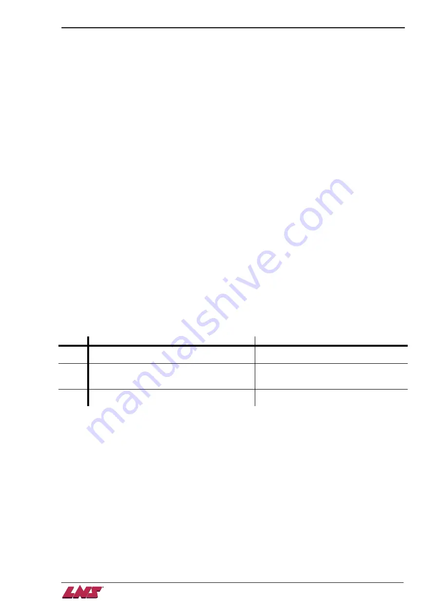
This relay energizes under circumstances below:
Index Beginning
End
1
The moment when the SHORT pusher leaves
the origin reference for proceeding FIRST FEED.
The moment that SHORT pusher returns to
the origin reference.
2
The moment when the LONG pusher leaves the
origin reference for proceeding TOP CUT
position.
The moment when the LONG pusher is
stopped after arriving at TOP CUT position.
3
The moment when the lathe chuck opens during
machining.
The moment when the LONG pusher is
stopped after it has moved to the part length.
Refer to service parameter MODE 16 for more information.
Summary of Contents for Eco Load S2
Page 1: ...LNS SA 2534 Orvin Switzerland www LNS group com Instruction manual ENG 9 ECO 01 ...
Page 2: ......
Page 5: ...CHAPTER 1 BASIC NOTIONS 1 1 ECOLOAD S2 CHAPTER 1 BASIC NOTIONS ...
Page 12: ...1 8 CHAPTER 1 BASIC NOTIONS ECOLOAD S2 ...
Page 13: ...CHAPTER 2 TECHNICAL DATA 2 1 ECOLOAD S2 CHAPTER 2 TECHNICAL DATA ...
Page 17: ...CHAPTER 2 TECHNICAL DATA 2 5 ECOLOAD S2 2 3 Z axis retraction system ˋˆˊ ˊˋˊ ˌˊ ˉ ˁˈ ʳ ˆˇ ˈ ...
Page 19: ...CHAPTER 3 SETTING INTO OPERATION 3 1 ECOLOAD S2 CHAPTER 3 SETTING INTO OPERATION ...
Page 36: ...3 18 CHAPTER 3 SETTING INTO OPERATION ECOLOAD S2 ...
Page 37: ...CHAPTER 4 ELECTRICS 4 1 ECOLOAD S2 CHAPTER 4 ELECTRICS ...
Page 43: ...CHAPTER 4 ELECTRICS 4 7 ECOLOAD S2 4 2 Circuit diagram ...
Page 45: ...CHAPTER 4 ELECTRICS 4 9 ECOLOAD S2 5 2 PLC I O DIAGRAMS ...
Page 54: ...4 18 CHAPTER 4 ELECTRICS ECOLOAD S2 ...
Page 55: ...CHAPTER 5 PNEUMATICS 5 1 ECOLOAD S2 CHAPTER 5 PNEUMATICS ...
Page 57: ...CHAPTER 5 PNEUMATICS 5 3 ECOLOAD S2 2 PNEUMATIC CIRCUIT DIAGRAM ...
Page 62: ...5 8 CHAPTER 5 PNEUMATICS ECOLOAD S2 ...
Page 63: ...CHAPTER 6 GENERAL DESCRIPTION 6 1 ECOLOAD S2 CHAPTER 6 GENERAL DESCRIPTION ...
Page 77: ...CHAPTER 7 OPERATION 7 1 ECOLOAD S2 CHAPTER 7 OPERATION ...
Page 98: ...7 22 CHAPTER 7 OPERATION ECOLOAD S2 ...
Page 99: ...CHAPTER 8 TROUBLESHOOTING GUIDE 8 1 ECOLOAD S2 CHAPTER 8 TROUBLESHOOTING GUIDE ...
Page 109: ...CHAPTER 9 APPENDICES 9 1 ECOLOAD S2 CHAPTER 9 APPENDICES ...


