CHAPTER 6: GENERAL DESCRIPTION
6-9
ECOLOAD S2
4.3. Pushing force adjustment
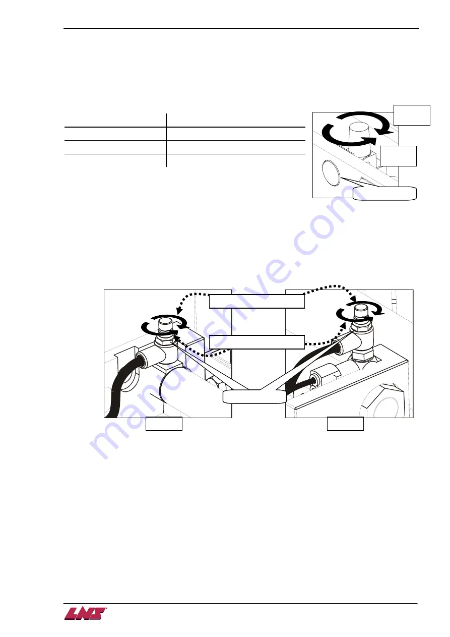
The pushing force could be changed by adjusting the air regulator according to the bar stock diameter.
Since the pushing force is reduced by various bar stock boundary conditions includes material density,
surface condition, rodless cylinder performance... and so forth, there is no firm recommended value for
specific bar stock diameter. But the user could set as the reference table below then adjust according to
real producing conditions.
Bar stock diameter (mm)
Suggested regulator pressure (bar)
below 10
3
10 ~ 30
3 ~ 4
above 30
4 ~ 6
Turn the knob clockwise to increase the pushing pressure and
turn it counter-clockwise to reduce it.
4.4. Damping force adjustment
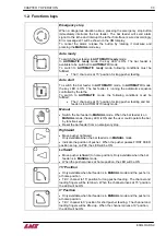
With the increasing pushing force, the impact might be larger when pusher arrives at the front or rear
limitation. To avoid this, the bar feeder allows the user to give damping effect on each end as shown
below. Turn the valve clockwise to increase the damping distance or turn it counter-clockwise to decrease
it.
Pressure gauge
Increase
pressure
Decrease
pressure
Lock/unlock
Increase damping distance
Rear end
Lock/unlock
Decrease damping distance
Front end
Summary of Contents for Eco Load S2
Page 1: ...LNS SA 2534 Orvin Switzerland www LNS group com Instruction manual ENG 9 ECO 01 ...
Page 2: ......
Page 5: ...CHAPTER 1 BASIC NOTIONS 1 1 ECOLOAD S2 CHAPTER 1 BASIC NOTIONS ...
Page 12: ...1 8 CHAPTER 1 BASIC NOTIONS ECOLOAD S2 ...
Page 13: ...CHAPTER 2 TECHNICAL DATA 2 1 ECOLOAD S2 CHAPTER 2 TECHNICAL DATA ...
Page 17: ...CHAPTER 2 TECHNICAL DATA 2 5 ECOLOAD S2 2 3 Z axis retraction system ˋˆˊ ˊˋˊ ˌˊ ˉ ˁˈ ʳ ˆˇ ˈ ...
Page 19: ...CHAPTER 3 SETTING INTO OPERATION 3 1 ECOLOAD S2 CHAPTER 3 SETTING INTO OPERATION ...
Page 36: ...3 18 CHAPTER 3 SETTING INTO OPERATION ECOLOAD S2 ...
Page 37: ...CHAPTER 4 ELECTRICS 4 1 ECOLOAD S2 CHAPTER 4 ELECTRICS ...
Page 43: ...CHAPTER 4 ELECTRICS 4 7 ECOLOAD S2 4 2 Circuit diagram ...
Page 45: ...CHAPTER 4 ELECTRICS 4 9 ECOLOAD S2 5 2 PLC I O DIAGRAMS ...
Page 54: ...4 18 CHAPTER 4 ELECTRICS ECOLOAD S2 ...
Page 55: ...CHAPTER 5 PNEUMATICS 5 1 ECOLOAD S2 CHAPTER 5 PNEUMATICS ...
Page 57: ...CHAPTER 5 PNEUMATICS 5 3 ECOLOAD S2 2 PNEUMATIC CIRCUIT DIAGRAM ...
Page 62: ...5 8 CHAPTER 5 PNEUMATICS ECOLOAD S2 ...
Page 63: ...CHAPTER 6 GENERAL DESCRIPTION 6 1 ECOLOAD S2 CHAPTER 6 GENERAL DESCRIPTION ...
Page 77: ...CHAPTER 7 OPERATION 7 1 ECOLOAD S2 CHAPTER 7 OPERATION ...
Page 98: ...7 22 CHAPTER 7 OPERATION ECOLOAD S2 ...
Page 99: ...CHAPTER 8 TROUBLESHOOTING GUIDE 8 1 ECOLOAD S2 CHAPTER 8 TROUBLESHOOTING GUIDE ...
Page 109: ...CHAPTER 9 APPENDICES 9 1 ECOLOAD S2 CHAPTER 9 APPENDICES ...


