CHAPTER 7: OPERATION
7-3
ECOLOAD S2
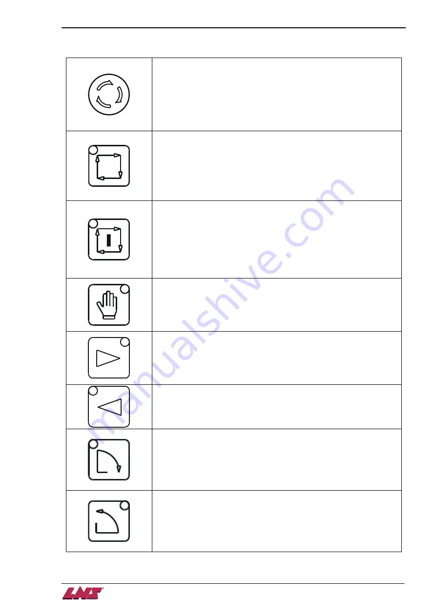
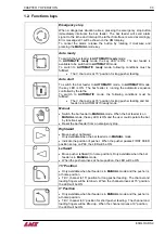
1.2. Functions keys
Emergency stop
When a dangerous situation arises, pressing the emergency stop button
immediately interrupts the bar feeder. The bar feeder will send alarm
signal to the lathe and interrupt the lathe if interface is wired accordingly.
Error message e01 will be shown on the HMI display.
To cancel the alarm, release the button by rotating it clockwise and
pressing the
MANUAL
mode key.
Auto ready
To switch the bar feeder to
AUTOMATIC ready
mode.
In
AUTOMATIC ready
mode, the key LED is ON. The bar feeder is
available to be switched to
AUTOMATIC
mode.
To switch to
AUTOMATIC ready
mode, following conditions must be
fulfilled:
The V channel is at 15° position for long pusher feeding.
Auto start
To switch the bar feeder to
AUTOMATIC
mode. In
AUTOMATIC
mode,
the key LED is ON. The bar feeder is running the automatic sequence
controlled by the lathe.
To switch to
AUTOMATIC
mode, the following conditions must be
fulfilled :
The V channel is at 15° position for long pusher feeding and bar
feeder is in AUTOMATIC ready mode.
Manual
Switch the bar feeder to
MANUAL
mode. When the bar feeder is on
MANUAL
mode, the key LED is ON and the user could operate the bar
by function keys.
Reset the bar feeder from an emergency stop.
Rightward
Move pusher rightward.
Only available when the bar feeder is in
MANUAL
mode
Indicate the position of pusher. When the pusher passes FIRST FEED
position set up on P08, the LED will be ON.
Leftward
Move pusher leftward (to home position). Only available when the bar
feeder is in
MANUAL
mode.
When the pusher arrives at home position, the LED will be ON.
15° Position
Only available when bar feeder is in
MANUAL
mode and the pusher is
at home position.
Tilt V channel to 15° position for long pusher feeding. The channel and
loading fingers will be let down. When the channel arrives at 15° position,
the LED will be ON.
0° Position
Only available when bar feeder is in
MANUAL
mode and the pusher is
at home position.
Tilt V channel to 0° position for short pusher feeding. The channel and
loading fingers will be lifted up. When the channel arrives at 0° position,
the LED will be ON.
Summary of Contents for Eco Load S2
Page 1: ...LNS SA 2534 Orvin Switzerland www LNS group com Instruction manual ENG 9 ECO 01 ...
Page 2: ......
Page 5: ...CHAPTER 1 BASIC NOTIONS 1 1 ECOLOAD S2 CHAPTER 1 BASIC NOTIONS ...
Page 12: ...1 8 CHAPTER 1 BASIC NOTIONS ECOLOAD S2 ...
Page 13: ...CHAPTER 2 TECHNICAL DATA 2 1 ECOLOAD S2 CHAPTER 2 TECHNICAL DATA ...
Page 17: ...CHAPTER 2 TECHNICAL DATA 2 5 ECOLOAD S2 2 3 Z axis retraction system ˋˆˊ ˊˋˊ ˌˊ ˉ ˁˈ ʳ ˆˇ ˈ ...
Page 19: ...CHAPTER 3 SETTING INTO OPERATION 3 1 ECOLOAD S2 CHAPTER 3 SETTING INTO OPERATION ...
Page 36: ...3 18 CHAPTER 3 SETTING INTO OPERATION ECOLOAD S2 ...
Page 37: ...CHAPTER 4 ELECTRICS 4 1 ECOLOAD S2 CHAPTER 4 ELECTRICS ...
Page 43: ...CHAPTER 4 ELECTRICS 4 7 ECOLOAD S2 4 2 Circuit diagram ...
Page 45: ...CHAPTER 4 ELECTRICS 4 9 ECOLOAD S2 5 2 PLC I O DIAGRAMS ...
Page 54: ...4 18 CHAPTER 4 ELECTRICS ECOLOAD S2 ...
Page 55: ...CHAPTER 5 PNEUMATICS 5 1 ECOLOAD S2 CHAPTER 5 PNEUMATICS ...
Page 57: ...CHAPTER 5 PNEUMATICS 5 3 ECOLOAD S2 2 PNEUMATIC CIRCUIT DIAGRAM ...
Page 62: ...5 8 CHAPTER 5 PNEUMATICS ECOLOAD S2 ...
Page 63: ...CHAPTER 6 GENERAL DESCRIPTION 6 1 ECOLOAD S2 CHAPTER 6 GENERAL DESCRIPTION ...
Page 77: ...CHAPTER 7 OPERATION 7 1 ECOLOAD S2 CHAPTER 7 OPERATION ...
Page 98: ...7 22 CHAPTER 7 OPERATION ECOLOAD S2 ...
Page 99: ...CHAPTER 8 TROUBLESHOOTING GUIDE 8 1 ECOLOAD S2 CHAPTER 8 TROUBLESHOOTING GUIDE ...
Page 109: ...CHAPTER 9 APPENDICES 9 1 ECOLOAD S2 CHAPTER 9 APPENDICES ...


