7-4
CHAPTER 7: OPERATION
ECOLOAD S2
2. HMI (Human Machine Interface)
The HMI allows the user to read messages and set parameters
2.1. Text display area
The display provides parameters, status information and error messages:
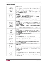
After powering up, the screen shown left is displayed. Press key
to switch to the parameter screen
as shown on the right.
In the parameter screen, 3 selections are available:
1.
: To access the OPERATION PARAMETER screen.
2.
: To access the SERVICE PARAMETER screen.
3.
: To display the software version. Both HMI and PLC has their own
software as shown. This information is sometimes necessary when you
contact us for technical support.
2.2. Status indication area
Alarm (red)
This LED will be ON when
powering up the bar feeder. After initialization of the HMI the LED will turn OFF.
there is a communication failure between the PLC and the HMI.
RS-232 (green)
The RS-232 interface is not used and the LED remains OFF.
RS-485 (green)
The RS-485 LED indicates communication activity between the PLC and HMI.
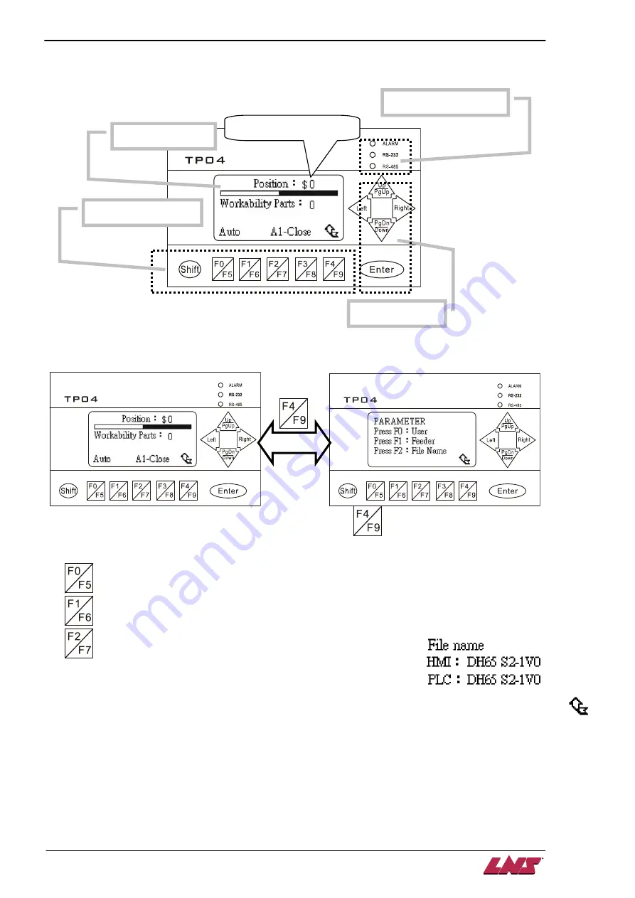
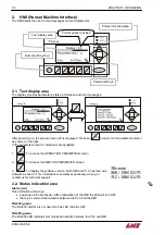
Text display area
Command Keys
Status indicating area
Current pusher position
Numerical Key Pad
Summary of Contents for Eco Load S2
Page 1: ...LNS SA 2534 Orvin Switzerland www LNS group com Instruction manual ENG 9 ECO 01 ...
Page 2: ......
Page 5: ...CHAPTER 1 BASIC NOTIONS 1 1 ECOLOAD S2 CHAPTER 1 BASIC NOTIONS ...
Page 12: ...1 8 CHAPTER 1 BASIC NOTIONS ECOLOAD S2 ...
Page 13: ...CHAPTER 2 TECHNICAL DATA 2 1 ECOLOAD S2 CHAPTER 2 TECHNICAL DATA ...
Page 17: ...CHAPTER 2 TECHNICAL DATA 2 5 ECOLOAD S2 2 3 Z axis retraction system ˋˆˊ ˊˋˊ ˌˊ ˉ ˁˈ ʳ ˆˇ ˈ ...
Page 19: ...CHAPTER 3 SETTING INTO OPERATION 3 1 ECOLOAD S2 CHAPTER 3 SETTING INTO OPERATION ...
Page 36: ...3 18 CHAPTER 3 SETTING INTO OPERATION ECOLOAD S2 ...
Page 37: ...CHAPTER 4 ELECTRICS 4 1 ECOLOAD S2 CHAPTER 4 ELECTRICS ...
Page 43: ...CHAPTER 4 ELECTRICS 4 7 ECOLOAD S2 4 2 Circuit diagram ...
Page 45: ...CHAPTER 4 ELECTRICS 4 9 ECOLOAD S2 5 2 PLC I O DIAGRAMS ...
Page 54: ...4 18 CHAPTER 4 ELECTRICS ECOLOAD S2 ...
Page 55: ...CHAPTER 5 PNEUMATICS 5 1 ECOLOAD S2 CHAPTER 5 PNEUMATICS ...
Page 57: ...CHAPTER 5 PNEUMATICS 5 3 ECOLOAD S2 2 PNEUMATIC CIRCUIT DIAGRAM ...
Page 62: ...5 8 CHAPTER 5 PNEUMATICS ECOLOAD S2 ...
Page 63: ...CHAPTER 6 GENERAL DESCRIPTION 6 1 ECOLOAD S2 CHAPTER 6 GENERAL DESCRIPTION ...
Page 77: ...CHAPTER 7 OPERATION 7 1 ECOLOAD S2 CHAPTER 7 OPERATION ...
Page 98: ...7 22 CHAPTER 7 OPERATION ECOLOAD S2 ...
Page 99: ...CHAPTER 8 TROUBLESHOOTING GUIDE 8 1 ECOLOAD S2 CHAPTER 8 TROUBLESHOOTING GUIDE ...
Page 109: ...CHAPTER 9 APPENDICES 9 1 ECOLOAD S2 CHAPTER 9 APPENDICES ...


