7-12
CHAPTER 7: OPERATION
ECOLOAD S2
5.2. Description
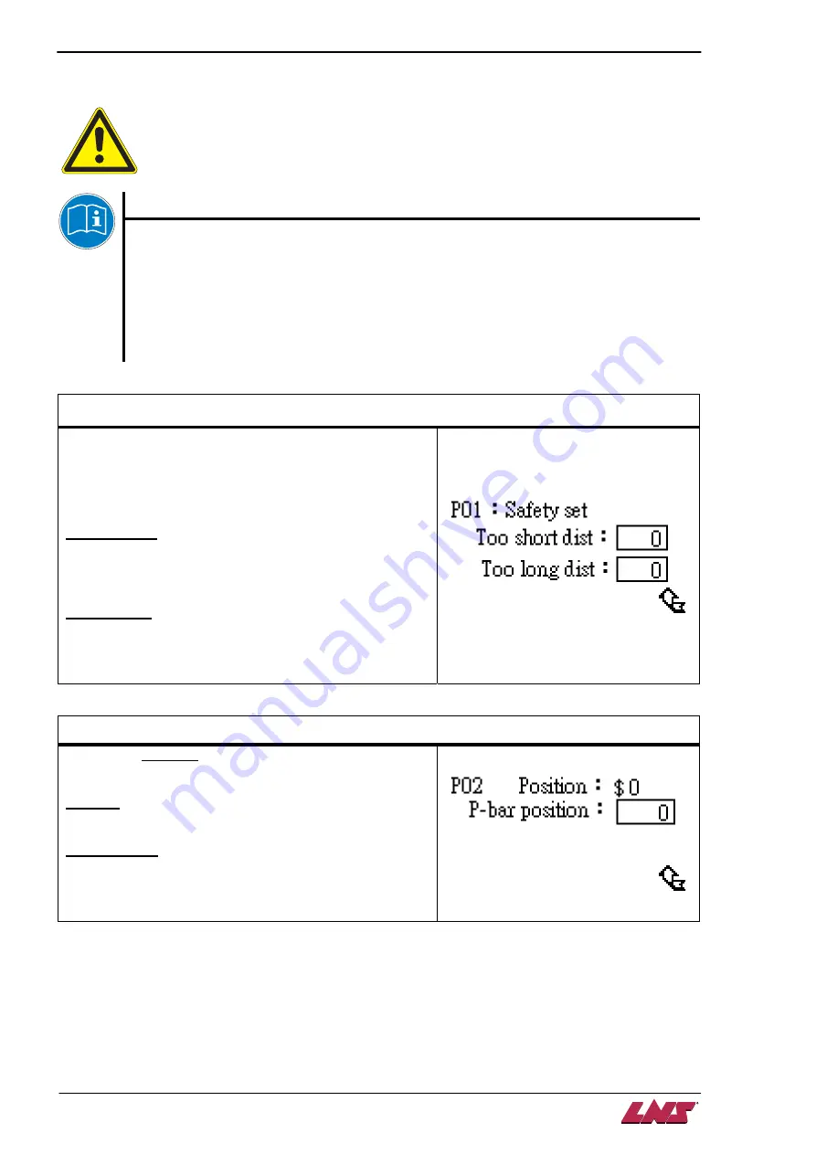
Only parameters inside rectangular are adjustable.
Unit for all the length / position related parameters is mm
.
The bar stock positioning control logic
The ECOLOAD S2 pusher was designed to be stopped with auxiliary of the stopper inside
the lathe. Whenever the chuck is open and the lathe is in automatic mode, the pusher feeds
forward all the time until it was stopped or arrives at end of its stroke.
When the pusher is stopped by the stopper (via bar stock), the bar feeder sends START
signal to the lathe via interface accordingly.
The lathe should never proceed any further action – the next machining cycle or bar change,
without this signal.
P01 Feeding distance check
This parameter should be MODIFIED if if
production part changed.
This setup allows the operator to assign the maximum and
minimum feeding distance that the bar feeder should alert.
When those values are exceeded, the bar feeder will arise
alarm accordingly.
Too short dist
The minimum allowed feeding distance. The bar feeder
arises an alarm if the feeding distance is smaller than this
value when chuck/collet is open.
Too long dist
The maximum allowed feeding distance. The bar feeder
arises an alarm if the feeding distance is larger than this
value either the chuck/collet is open or close.
P02 Pusher retract position 2 of 2
The pusher retraction
POSITION
to avoid its tip contacting
with rotating spindle. Refer to P04 for reference.
Position
Current pusher position measured from home position SR3.
P-bar position
The
POSITION
where the pusher should be
POSITIONED
so that its tip does not droop and contact the rotating
spindle.
Summary of Contents for Eco Load S2
Page 1: ...LNS SA 2534 Orvin Switzerland www LNS group com Instruction manual ENG 9 ECO 01 ...
Page 2: ......
Page 5: ...CHAPTER 1 BASIC NOTIONS 1 1 ECOLOAD S2 CHAPTER 1 BASIC NOTIONS ...
Page 12: ...1 8 CHAPTER 1 BASIC NOTIONS ECOLOAD S2 ...
Page 13: ...CHAPTER 2 TECHNICAL DATA 2 1 ECOLOAD S2 CHAPTER 2 TECHNICAL DATA ...
Page 17: ...CHAPTER 2 TECHNICAL DATA 2 5 ECOLOAD S2 2 3 Z axis retraction system ˋˆˊ ˊˋˊ ˌˊ ˉ ˁˈ ʳ ˆˇ ˈ ...
Page 19: ...CHAPTER 3 SETTING INTO OPERATION 3 1 ECOLOAD S2 CHAPTER 3 SETTING INTO OPERATION ...
Page 36: ...3 18 CHAPTER 3 SETTING INTO OPERATION ECOLOAD S2 ...
Page 37: ...CHAPTER 4 ELECTRICS 4 1 ECOLOAD S2 CHAPTER 4 ELECTRICS ...
Page 43: ...CHAPTER 4 ELECTRICS 4 7 ECOLOAD S2 4 2 Circuit diagram ...
Page 45: ...CHAPTER 4 ELECTRICS 4 9 ECOLOAD S2 5 2 PLC I O DIAGRAMS ...
Page 54: ...4 18 CHAPTER 4 ELECTRICS ECOLOAD S2 ...
Page 55: ...CHAPTER 5 PNEUMATICS 5 1 ECOLOAD S2 CHAPTER 5 PNEUMATICS ...
Page 57: ...CHAPTER 5 PNEUMATICS 5 3 ECOLOAD S2 2 PNEUMATIC CIRCUIT DIAGRAM ...
Page 62: ...5 8 CHAPTER 5 PNEUMATICS ECOLOAD S2 ...
Page 63: ...CHAPTER 6 GENERAL DESCRIPTION 6 1 ECOLOAD S2 CHAPTER 6 GENERAL DESCRIPTION ...
Page 77: ...CHAPTER 7 OPERATION 7 1 ECOLOAD S2 CHAPTER 7 OPERATION ...
Page 98: ...7 22 CHAPTER 7 OPERATION ECOLOAD S2 ...
Page 99: ...CHAPTER 8 TROUBLESHOOTING GUIDE 8 1 ECOLOAD S2 CHAPTER 8 TROUBLESHOOTING GUIDE ...
Page 109: ...CHAPTER 9 APPENDICES 9 1 ECOLOAD S2 CHAPTER 9 APPENDICES ...


