3-8
Chapter 3: Procedures
HYDROBAR EXPRESS 220
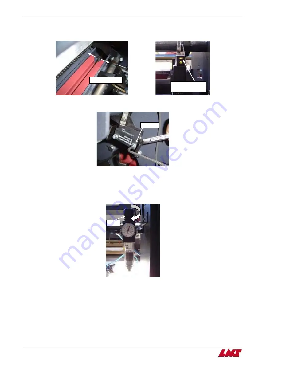
Step 8: Roll the bar stock across the width of the guiding channel and check to see that the sensor is centered over the material.
The light on SQ1 will illuminate if the sensor is centered. If not, continue to the next step. If the sensor is centered, skip to
step 11.
Step 9: Using a 2.5mm hex key and 7mm combination wrench, loosen and adjust the front bolt on SQ1 accordingly so that it picks
up the bar stock and the light on SQ1 illuminates.
Step 10: Retighten the bolt holding the sensor in pl
e
y repeating step 8.
Step 11: Remove the short piece of material.
Step 12: Remove the 8 or 11 mm guiding channel and replace the correct guiding channel size according to the bar stock used.
Step 13: Pull up on the air regulator knob and turn it clockwise and set the air pressure to the sixth bar (90 psi).
ace and r check the settings b
Procedure complete.
Front bolt
Knob
Light will illuminate
if SQ1 is centered
Roll the bar stock
Summary of Contents for Hydrobar Express 220
Page 61: ......
Page 143: ......
Page 147: ......
Page 156: ...Chapter 6 Spare Parts 6 9 HYDROBAR EXPRESS 220 Servo Motor Assembly ...
Page 161: ...6 14 Chapter 6 Spare Parts HYDROBAR EXPRESS 220 Hydraulic Pump Assembly ...
Page 163: ...6 16 Chapter 6 Spare Parts HYDROBAR EXPRESS 220 Diameter Adjustment Motor Assembly ...
Page 164: ...Chapter 6 Spare Parts 6 17 HYDROBAR EXPRESS 220 Air Regulator and Cable Passage Plate ...


