


C H A P T E R 1 : A L A R M S
1 - 2 6
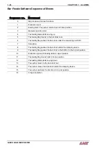
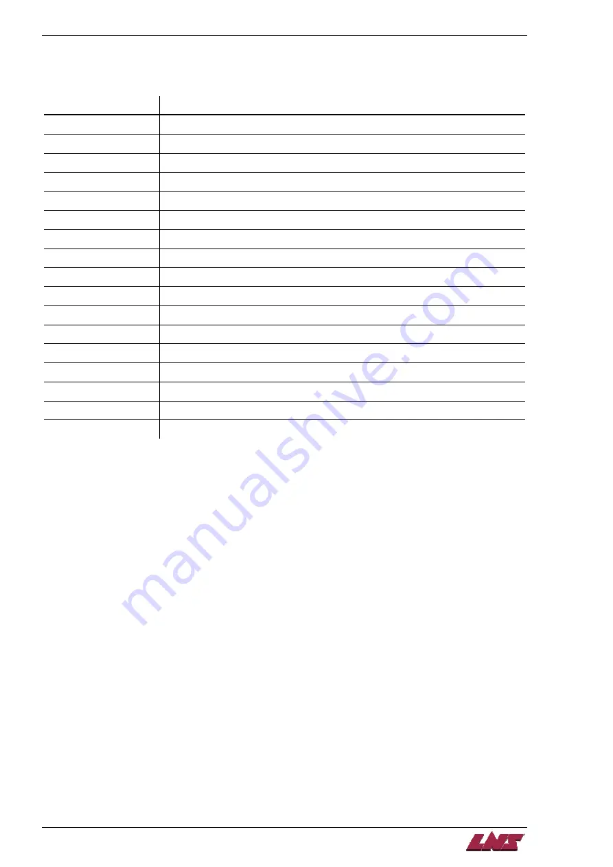
Bar Feeder Software Sequence of Events
Sequence no. Movement
0
Stop mode and manual functions
1 Production
cycle.
2
Loading start. The pusher returns back to home position.
3 Diameter
selection
start.
4
The loading table starts moving up
5
The loading flag moves to the bar stock rear.
6
The loading flag pushes the bar stock under the measuring cell SQ3
7 Calculation
8
The loading flag pushes the bar stock behind the clamping device.
9
The loading flag pushes the bar stock to the EOB or to the top cut position.
10
Production cycle with loading table in upper position.
11
The loading flag moves back to home position.
12
The loading table starts moving down.
13
The pusher moves to the bar stock rear.
14
The pusher moves the bar stock behind the clamping device.
15
The pusher positions the bar stock in top cut position
16
In top cut position.
QUICK LOAD SERVO 65/80
Summary of Contents for Quick Load Servo 65
Page 1: ...Troubleshooting manual ENG 9 020 01 ANG ...
Page 43: ......
Page 61: ......
Page 67: ......
Page 96: ...CHAPTER 6 SPARE PARTS QUICK LOAD SERVO 65 80 6 27 020 005 413 QLS 65 80 Locking block ...
Page 99: ...CHAPTER 6 SPARE PARTS 6 30 020 005 703 QLS 65 80 Sub assembly drive QUICK LOAD SERVO 65 80 ...
Page 101: ...CHAPTER 6 SPARE PARTS 6 32 020 005 723 QLS 65 80 Sub assembly cogwheel QUICK LOAD SERVO 65 80 ...
Page 115: ...CHAPTER 6 SPARE PARTS 6 46 020 011 013 12 QLS 65 Assembly pusher ø12 QUICK LOAD SERVO 65 80 ...
Page 116: ...CHAPTER 6 SPARE PARTS QUICK LOAD SERVO 65 80 6 47 020 011 013 20 QLS 65 Assembly pusher ø20 ...
Page 117: ...CHAPTER 6 SPARE PARTS 6 48 020 011 023 6 QLS 80 Assembly pusher ø1 4 QUICK LOAD SERVO 65 80 ...
Page 118: ...CHAPTER 6 SPARE PARTS QUICK LOAD SERVO 65 80 6 49 020 011 023 12 QLS 80 Assembly pusher ø12 ...
Page 119: ...CHAPTER 6 SPARE PARTS 6 50 020 011 023 20 QLS 80 Assembly pusher ø20 QUICK LOAD SERVO 65 80 ...


