


C H A P T E R 3 : P R O C E D U R E S
QUICK LOAD SERVO 65/80
3 - 3
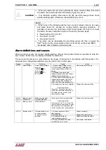
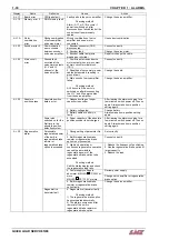
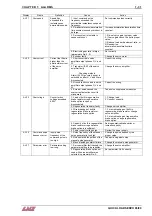
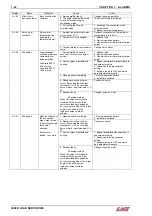
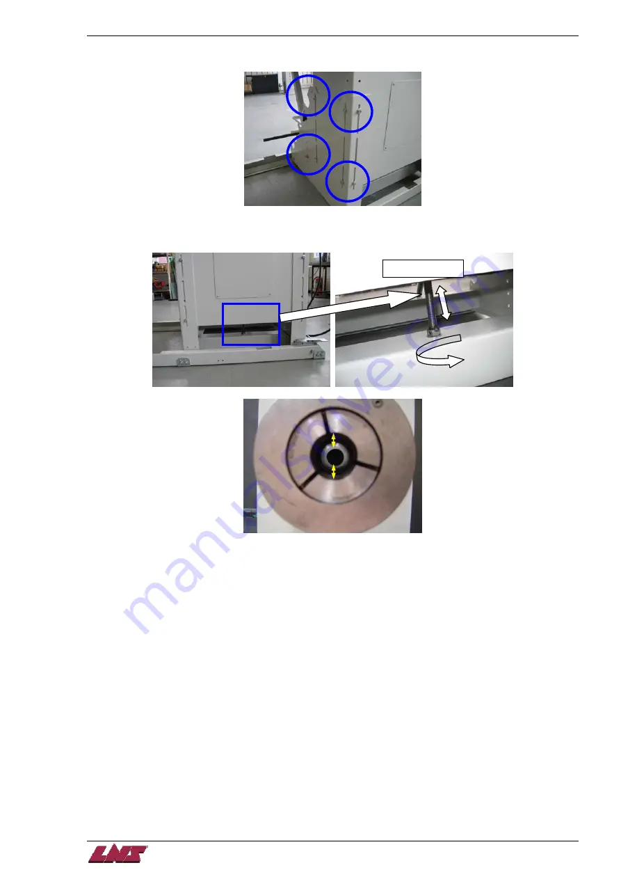
Step 3:
Carefully loosen the 12 screws located in the slots on the base of the unit (6 each side). This will allow the
unit to be adjusted up and down.
Step 4:
Using the central jackscrew, adjust the unit so that the pusher is centered up and down at the back of the
spindle. Make sure that the unit raises or lowers uniformly.
Central jackscrew
Summary of Contents for Quick Load Servo 65
Page 1: ...Troubleshooting manual ENG 9 020 01 ANG ...
Page 43: ......
Page 61: ......
Page 67: ......
Page 96: ...CHAPTER 6 SPARE PARTS QUICK LOAD SERVO 65 80 6 27 020 005 413 QLS 65 80 Locking block ...
Page 99: ...CHAPTER 6 SPARE PARTS 6 30 020 005 703 QLS 65 80 Sub assembly drive QUICK LOAD SERVO 65 80 ...
Page 101: ...CHAPTER 6 SPARE PARTS 6 32 020 005 723 QLS 65 80 Sub assembly cogwheel QUICK LOAD SERVO 65 80 ...
Page 115: ...CHAPTER 6 SPARE PARTS 6 46 020 011 013 12 QLS 65 Assembly pusher ø12 QUICK LOAD SERVO 65 80 ...
Page 116: ...CHAPTER 6 SPARE PARTS QUICK LOAD SERVO 65 80 6 47 020 011 013 20 QLS 65 Assembly pusher ø20 ...
Page 117: ...CHAPTER 6 SPARE PARTS 6 48 020 011 023 6 QLS 80 Assembly pusher ø1 4 QUICK LOAD SERVO 65 80 ...
Page 118: ...CHAPTER 6 SPARE PARTS QUICK LOAD SERVO 65 80 6 49 020 011 023 12 QLS 80 Assembly pusher ø12 ...
Page 119: ...CHAPTER 6 SPARE PARTS 6 50 020 011 023 20 QLS 80 Assembly pusher ø20 QUICK LOAD SERVO 65 80 ...


