3 -
C H A P T E R 3 : P R O C E D U R E S
3 - 4
Step 5:
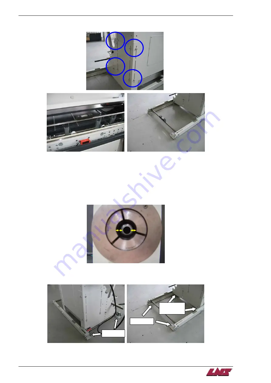
Once the pusher is centered up and down, tighten the 12 screws to secure unit and recheck the level of
the unit.
Step 6:
Align the unit side to side by centering the pusher in the back of the spindle and then extending the pusher
to the back of the collet and centering it there.
Adjust the rear of the bar feed when centering to the rear of the spindle and the front of the bar feed when
centering to the rear of the collet.
Once the pusher is centered at the back of the collet recheck the alignment at the back of the spindle by
pulling the pusher back. Continue until the pusher is centered at the rear of the spindle and at the rear of
the collet.
Step 7:
Once the bar feed has been aligned anchor it using the 4 anchor bolts supplied with the unit. Don't anchor
it at retract rail centers; just let the screws touch the ground.
Anchor here
Don’t anchor
here!!!
Anchor here
QUICK LOAD SERVO 65/80
Summary of Contents for Quick Load Servo 65
Page 1: ...Troubleshooting manual ENG 9 020 01 ANG ...
Page 43: ......
Page 61: ......
Page 67: ......
Page 96: ...CHAPTER 6 SPARE PARTS QUICK LOAD SERVO 65 80 6 27 020 005 413 QLS 65 80 Locking block ...
Page 99: ...CHAPTER 6 SPARE PARTS 6 30 020 005 703 QLS 65 80 Sub assembly drive QUICK LOAD SERVO 65 80 ...
Page 101: ...CHAPTER 6 SPARE PARTS 6 32 020 005 723 QLS 65 80 Sub assembly cogwheel QUICK LOAD SERVO 65 80 ...
Page 115: ...CHAPTER 6 SPARE PARTS 6 46 020 011 013 12 QLS 65 Assembly pusher ø12 QUICK LOAD SERVO 65 80 ...
Page 116: ...CHAPTER 6 SPARE PARTS QUICK LOAD SERVO 65 80 6 47 020 011 013 20 QLS 65 Assembly pusher ø20 ...
Page 117: ...CHAPTER 6 SPARE PARTS 6 48 020 011 023 6 QLS 80 Assembly pusher ø1 4 QUICK LOAD SERVO 65 80 ...
Page 118: ...CHAPTER 6 SPARE PARTS QUICK LOAD SERVO 65 80 6 49 020 011 023 12 QLS 80 Assembly pusher ø12 ...
Page 119: ...CHAPTER 6 SPARE PARTS 6 50 020 011 023 20 QLS 80 Assembly pusher ø20 QUICK LOAD SERVO 65 80 ...

