C H A P T E R 3 : P R O C E D U R E S
QUICK LOAD SERVO 65/80
3 - 7
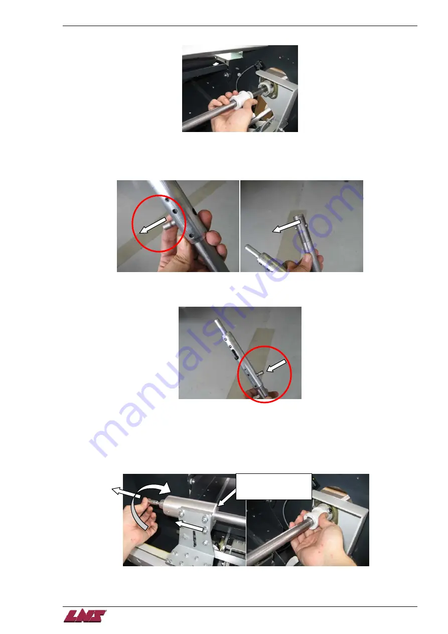
Step 4:
Pull the white bushing on the front guide bearing towards the rear of the bar feed to extract it.
Step 5:
Remove the pusher completely from the bar feed.
Step 6:
Disassemble the pusher adapter from the pusher body by pushing out the crossing shaft. Reset the shaft
in the pusher body to avoid losing it.
Step 7:
Assemble the pusher adapter on the new pusher body with the corresponding shaft.
Step 8:
Put the corresponding white bushing on the pusher. Insert the front end of the pusher through the front of
the bar feed first, then slide the pusher adapter through the carrier so that it is flush on the right hand side
of the carrier.
Step 9:
When the pusher adapter is in place in the carrier, turn the finger ¼ of a turn back (counter-clockwise). The
finger must stay locked in rear position and the pusher must be totally locked into the carrier. Slide the
white bushing into the front guide bearing.
Must be flush on the
right side of the carrier
bushing.
Summary of Contents for Quick Load Servo 65
Page 1: ...Troubleshooting manual ENG 9 020 01 ANG ...
Page 43: ......
Page 61: ......
Page 67: ......
Page 96: ...CHAPTER 6 SPARE PARTS QUICK LOAD SERVO 65 80 6 27 020 005 413 QLS 65 80 Locking block ...
Page 99: ...CHAPTER 6 SPARE PARTS 6 30 020 005 703 QLS 65 80 Sub assembly drive QUICK LOAD SERVO 65 80 ...
Page 101: ...CHAPTER 6 SPARE PARTS 6 32 020 005 723 QLS 65 80 Sub assembly cogwheel QUICK LOAD SERVO 65 80 ...
Page 115: ...CHAPTER 6 SPARE PARTS 6 46 020 011 013 12 QLS 65 Assembly pusher ø12 QUICK LOAD SERVO 65 80 ...
Page 116: ...CHAPTER 6 SPARE PARTS QUICK LOAD SERVO 65 80 6 47 020 011 013 20 QLS 65 Assembly pusher ø20 ...
Page 117: ...CHAPTER 6 SPARE PARTS 6 48 020 011 023 6 QLS 80 Assembly pusher ø1 4 QUICK LOAD SERVO 65 80 ...
Page 118: ...CHAPTER 6 SPARE PARTS QUICK LOAD SERVO 65 80 6 49 020 011 023 12 QLS 80 Assembly pusher ø12 ...
Page 119: ...CHAPTER 6 SPARE PARTS 6 50 020 011 023 20 QLS 80 Assembly pusher ø20 QUICK LOAD SERVO 65 80 ...


