C H A P T E R 3 : P R O C E D U R E S
QUICK LOAD SERVO 65/80
3 - 9
Belt Tension Adjustment
Conditions:
-
Bar feed on.
-
Loading table in lower position.
-
Pusher at the mechanical home position.
-
Bar feed in
STOP
mode.
Procedure:
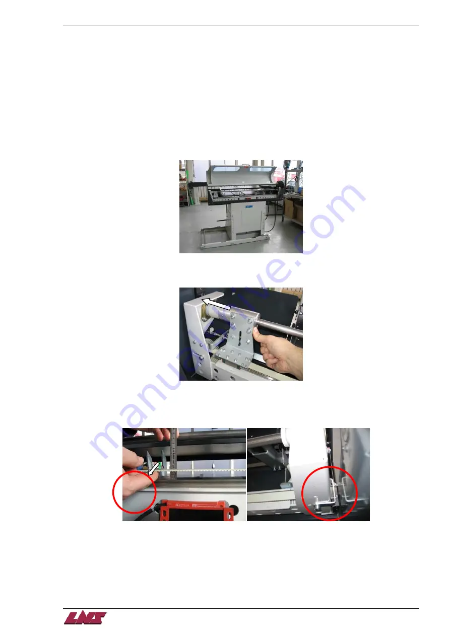
Step 1:
Open the main access cover.
Step 2:
Make sure the carrier is in home position.
Step 3:
In the middle of the linear rail, measure the belt vertical displacement from the belt to the rail. Don't force it
! This displacement must be approx. 20 mm. If necessary, modify the belt tension with the belt tensioner
located at the front of the bar feed.
Step 4:
Once the tension is set, close the main access cover.
Procedure complete.
Summary of Contents for Quick Load Servo 65
Page 1: ...Troubleshooting manual ENG 9 020 01 ANG ...
Page 43: ......
Page 61: ......
Page 67: ......
Page 96: ...CHAPTER 6 SPARE PARTS QUICK LOAD SERVO 65 80 6 27 020 005 413 QLS 65 80 Locking block ...
Page 99: ...CHAPTER 6 SPARE PARTS 6 30 020 005 703 QLS 65 80 Sub assembly drive QUICK LOAD SERVO 65 80 ...
Page 101: ...CHAPTER 6 SPARE PARTS 6 32 020 005 723 QLS 65 80 Sub assembly cogwheel QUICK LOAD SERVO 65 80 ...
Page 115: ...CHAPTER 6 SPARE PARTS 6 46 020 011 013 12 QLS 65 Assembly pusher ø12 QUICK LOAD SERVO 65 80 ...
Page 116: ...CHAPTER 6 SPARE PARTS QUICK LOAD SERVO 65 80 6 47 020 011 013 20 QLS 65 Assembly pusher ø20 ...
Page 117: ...CHAPTER 6 SPARE PARTS 6 48 020 011 023 6 QLS 80 Assembly pusher ø1 4 QUICK LOAD SERVO 65 80 ...
Page 118: ...CHAPTER 6 SPARE PARTS QUICK LOAD SERVO 65 80 6 49 020 011 023 12 QLS 80 Assembly pusher ø12 ...
Page 119: ...CHAPTER 6 SPARE PARTS 6 50 020 011 023 20 QLS 80 Assembly pusher ø20 QUICK LOAD SERVO 65 80 ...


