2 -
C H A P T E R 2 : C O M M O N I S S U E S
2 - 2
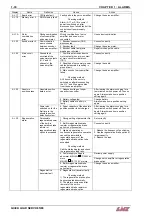
Vibrations
Description:
The term “vibration” is being used regarding the Quick Load Servo 65 / 80, to indicate that the RPM
performance of the lathe is physically deteriorated, to the point of creating an unbalanced rotational
oscillation of the bar stock, within the confines of the spindle of the lathe that is detrimental to the
machining process.
Various items can cause or enhance a lathe spindle vibration issue, requiring the reduction of the spindle
rpm to bring the anomaly back to a normal controlled rotation. These items can be related to the material,
the lathe, or the bar feed.
Note: The bar feed must be installed according to LNS specifications.
Possible Causes
Solutions
•
Lathe
leveling
•
The lathe should be level and on a solid foundation. LNS
recommend that the lathe be bolted to the floor.
•
Bad
alignment
between
the lathe and the bar
feeder;
•
Check the alignment between the lathe and the bar
feeder;
•
Check that the pusher does not touch anything while the
spindle is turning;
•
Wrong choice of the reduction tube diameter;
•
Ensure that the properly sized spindle liner has been
installed (1mm ideal gap);
•
Check the bar stock straightness (may be caught in a bind
into the spindle liner);
•
Ensure the liner is straight (check total run out), and has
all o-rings intact;
•
Bar stock material:
Aluminum: should not generate any vibrations
Steel: should not generate any vibrations
Inox steel: can generate some vibrations
Brass, copper and other soft materials: can
generate some vibrations without affecting the
machined part.
•
Test with standard steel or aluminum bar stock.
•
Material
profile
•
Round bars should rotate without noise
Profiled bars should generate acceptable noise/vibration.
•
Bar
straightness
A straightness of 0.5 mm for 1000 mm is
admissible.
•
Cut a bar stock in 2 and test; if the results are much
better, this is an evidence about the bad bar straightness.
•
Bar stock finish
•
If the material has been saw cut, the sharp edges and
burrs must be removed
•
If the material is a hot roll type it may not meet our
specifications.
•
If the material has been “cropped” to length the last 6”-12”
of the end of the bar may be unusable due to being bent
severely in the process.
Note: Also, there is a possibility to have a severe angle on the end of the bar, which has been cropped.
This can lead to mis-positioning during part feed out, depending on the surface area that the Quick Load’s
pusher is pushing against, as the bar has rotated in it’s orientation inside the spindle.
The headstock / actuator assembly should have minimal run out. *
Proper chucking device should be selected to match the machining application. *
The chucking device should have proper clamping pressure. *
The surface of the jaws or pads must make proper contact with the material. *
*Please reference OEM specifications.
QUICK LOAD SERVO 65/80
Summary of Contents for Quick Load Servo 65
Page 1: ...Troubleshooting manual ENG 9 020 01 ANG ...
Page 43: ......
Page 61: ......
Page 67: ......
Page 96: ...CHAPTER 6 SPARE PARTS QUICK LOAD SERVO 65 80 6 27 020 005 413 QLS 65 80 Locking block ...
Page 99: ...CHAPTER 6 SPARE PARTS 6 30 020 005 703 QLS 65 80 Sub assembly drive QUICK LOAD SERVO 65 80 ...
Page 101: ...CHAPTER 6 SPARE PARTS 6 32 020 005 723 QLS 65 80 Sub assembly cogwheel QUICK LOAD SERVO 65 80 ...
Page 115: ...CHAPTER 6 SPARE PARTS 6 46 020 011 013 12 QLS 65 Assembly pusher ø12 QUICK LOAD SERVO 65 80 ...
Page 116: ...CHAPTER 6 SPARE PARTS QUICK LOAD SERVO 65 80 6 47 020 011 013 20 QLS 65 Assembly pusher ø20 ...
Page 117: ...CHAPTER 6 SPARE PARTS 6 48 020 011 023 6 QLS 80 Assembly pusher ø1 4 QUICK LOAD SERVO 65 80 ...
Page 118: ...CHAPTER 6 SPARE PARTS QUICK LOAD SERVO 65 80 6 49 020 011 023 12 QLS 80 Assembly pusher ø12 ...
Page 119: ...CHAPTER 6 SPARE PARTS 6 50 020 011 023 20 QLS 80 Assembly pusher ø20 QUICK LOAD SERVO 65 80 ...

