2 -
C H A P T E R 2 : C O M M O N I S S U E S
2 - 4
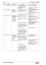
Part feed out accuracy
Description:
The accuracy of the part positioning can be affected by many factors. Choosing the correct bar feed
application and setting the barfeed parameters correctly are crucial to ensuring the proper accuracy.
Part Setup Parameter:
1. Input overall part length (Located in: 1. Part setup menu)
The parameter determines how far the push rod will advance the bar stock during a part feed out.
This value should include the finished part length, cut-off and facing. In other words, the amount
of material needed to make a complete part.
Application Selection: (Located in: 2. Application Setup)
1. Feed without help of the turret
This application requires that the lathe be equipped with a pull-to-close type clamping system. If a
push-to-close type clamping system is used then the “Feed with help of the turret” application
must be selected. It is recommended by LNS that when feeding without the help of the turret that
a dead-length, parallel gripping type clamping device be used. This type of clamping system will
prevent the bar stock from moving forward when the clamping device is closed, thus losing the
positioning accuracy.
2. Feed with help of the turret
This application can be selected when either a pull-to close or push-to-close type clamping
system is installed but must always be selected when a push-to-close type clamping system is
installed. This is due to the bar stock moving forward as the draw tube pushes forward to close
the clamping device.
Parameters related to clamping device: (located in: 4. Miscellaneous Functions menu)
1. Time for clamping device to close
Once the clamping device close signal is output from the lathe the barfeed will wait for the time
entered in this parameter to expire then the push rod will reverse off the back of the part.
If this time is set to low then the push rod may reverse before the clamping device is physically
closed. When this occurs with a pull-to-close clamping system then the push rod will not be in
place to support the bar stock as the clamping device closes. The push rod can overcome the
weight of the barstock moving in the draw tube but can not overcome the force of the clamping
device this is why a dead-length, parallel gripping type clamping device is recommended.
Setting this time to high will not effect the part positioning. However, if this time is set to high the
push rod may not reverse off the bar stock before the spindle begins to rotate. This can create
excessive noise and possibly damage the push rod.
QUICK LOAD SERVO 65/80
Summary of Contents for Quick Load Servo 65
Page 1: ...Troubleshooting manual ENG 9 020 01 ANG ...
Page 43: ......
Page 61: ......
Page 67: ......
Page 96: ...CHAPTER 6 SPARE PARTS QUICK LOAD SERVO 65 80 6 27 020 005 413 QLS 65 80 Locking block ...
Page 99: ...CHAPTER 6 SPARE PARTS 6 30 020 005 703 QLS 65 80 Sub assembly drive QUICK LOAD SERVO 65 80 ...
Page 101: ...CHAPTER 6 SPARE PARTS 6 32 020 005 723 QLS 65 80 Sub assembly cogwheel QUICK LOAD SERVO 65 80 ...
Page 115: ...CHAPTER 6 SPARE PARTS 6 46 020 011 013 12 QLS 65 Assembly pusher ø12 QUICK LOAD SERVO 65 80 ...
Page 116: ...CHAPTER 6 SPARE PARTS QUICK LOAD SERVO 65 80 6 47 020 011 013 20 QLS 65 Assembly pusher ø20 ...
Page 117: ...CHAPTER 6 SPARE PARTS 6 48 020 011 023 6 QLS 80 Assembly pusher ø1 4 QUICK LOAD SERVO 65 80 ...
Page 118: ...CHAPTER 6 SPARE PARTS QUICK LOAD SERVO 65 80 6 49 020 011 023 12 QLS 80 Assembly pusher ø12 ...
Page 119: ...CHAPTER 6 SPARE PARTS 6 50 020 011 023 20 QLS 80 Assembly pusher ø20 QUICK LOAD SERVO 65 80 ...

