3 -
C H A P T E R 3 : P R O C E D U R E S
3 - 2
Alignment Procedure
Conditions:
-
Bar feed power on.
Procedure:
Step 1:
Position the bar feed as close as possible to the rear of the lathe. The distance between the front of the
bar feed and the back of the spindle should be as small as possible.
Note: If obstacles prevent the bar feed from being positioned within 200 mm of the back of the
spindle an extension will be required.
Step 2:
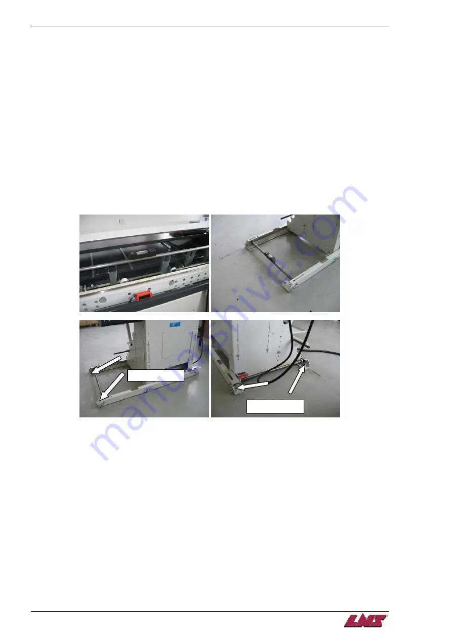
Level the bar feed in the x and y axis using a torpedo level. The level can be placed on the linear belt rail
to verify the y-axis and on the retract rails to verify the x-axis. Use the leveling screws on the retract to
adjust unit to level.
Leveling screws
Leveling screws
QUICK LOAD SERVO 65/80
Summary of Contents for Quick Load Servo 65
Page 1: ...Troubleshooting manual ENG 9 020 01 ANG ...
Page 43: ......
Page 61: ......
Page 67: ......
Page 96: ...CHAPTER 6 SPARE PARTS QUICK LOAD SERVO 65 80 6 27 020 005 413 QLS 65 80 Locking block ...
Page 99: ...CHAPTER 6 SPARE PARTS 6 30 020 005 703 QLS 65 80 Sub assembly drive QUICK LOAD SERVO 65 80 ...
Page 101: ...CHAPTER 6 SPARE PARTS 6 32 020 005 723 QLS 65 80 Sub assembly cogwheel QUICK LOAD SERVO 65 80 ...
Page 115: ...CHAPTER 6 SPARE PARTS 6 46 020 011 013 12 QLS 65 Assembly pusher ø12 QUICK LOAD SERVO 65 80 ...
Page 116: ...CHAPTER 6 SPARE PARTS QUICK LOAD SERVO 65 80 6 47 020 011 013 20 QLS 65 Assembly pusher ø20 ...
Page 117: ...CHAPTER 6 SPARE PARTS 6 48 020 011 023 6 QLS 80 Assembly pusher ø1 4 QUICK LOAD SERVO 65 80 ...
Page 118: ...CHAPTER 6 SPARE PARTS QUICK LOAD SERVO 65 80 6 49 020 011 023 12 QLS 80 Assembly pusher ø12 ...
Page 119: ...CHAPTER 6 SPARE PARTS 6 50 020 011 023 20 QLS 80 Assembly pusher ø20 QUICK LOAD SERVO 65 80 ...

